6.2.2.1. Fixed
A fixed joint always corresponds to two markers. It has zero degrees of freedom for the rotation and the translation.
It locks two parts together so they cannot move with respect to each other. The effect is similar to defining two parts as a single part. If the user wants to have the two parts moved relative to each other in the simulation, simply delete the fixed joint and use another type of joint. For a fixed joint, the location and orientation of the joint often do not affect the outcome of the simulation.
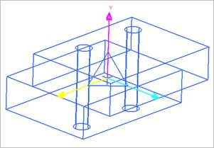
Figure 6.147 Fixed Joint icon on Working Window
6.2.2.1.1. Modeling Options
The user can create a joint entity as follows.
Point
Point: Selects a point on two bodies to define the location of a fixed joint.
Body, Body, Point
Body: Selects a base body of fixed joint.
Body: Selects an action body of fixed joint.
Point: Selects a point to define the location of a fixed joint.
Body, Multibody
Body: Selects a base body of the fixed joint.
Multibody: Selects action bodies of the fixed joint. The location of the fixed joint is to be CM marker of the action body.
Body, Body, MultiPoint
Body: Selects a base body of fixed joints.
Body: Selects an action body of fixed joints.
MultiPoint: Selects points to define locations of fixed joints.
6.2.2.1.2. Properties
The user can only define the force display using the Joint page.
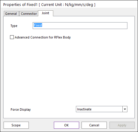
Figure 6.148 Fixed property page [Joint page]
Type: Shows the type of joint.
Advanced Connection for RFlex Body: If the user selects this option, the fixed joint is directly connected two bodies not using a virtual body connection. If there’s no RFlex body (Rigid or FFlex), this option is ignored.
Force Display: Displays the resultant force vector graphically on Working Window.