10.2.4.2. Generation of Input File
This section explains how to generate RecurDyn/Flex Input File (RFI) file from I-DEAS.
This example is a simple plate model. This plate is meshed with thin shell element with steel material property. You can get universal file through super element analysis with prg file. This universal file has FE information which includes node, element, property, material, mass, frequency, mode shape and etc. Mode shape is consisted of the orthonormalized normal modes which are resulted from vibration normal modes and static correction modes.
10.2.4.2.1. Modal Analysis
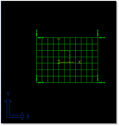
Figure 10.69 Target model
Run I-DEAS and create model.
Move to Master Modeler.
Create a geometric entity.
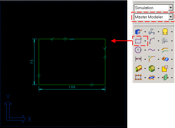
Figure 10.70 Creation of line
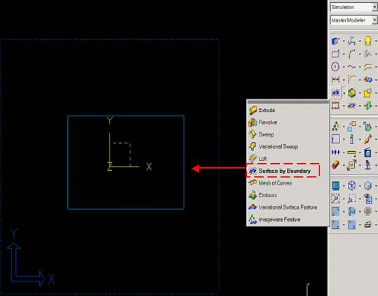
Figure 10.71 Define surface
Define FE model.
Move to Meshing.
Define Element
Select Define shell mesh.
You can define mesh about plate model in ‘Define mesh’ window. That is, you can change element type, element length and etc.
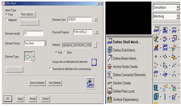
Figure 10.72 Defining mesh
Make a FE entity
Choose meshing method
Generate node and element
After choosing the method, select the part and enter. Then you can see the node and element numbers which are generated (Result information) in the top left side on the working window
Click Yes
If you don’t want to auto mesh, then you can make a node wherever you want and can also generate element with this node
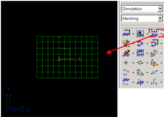
Figure 10.73 Mesh geometry
Define DOF set
Move to Boundary Conditions
Create boundary set
Select nodes that are constrained by applied by a force in the flexible body.
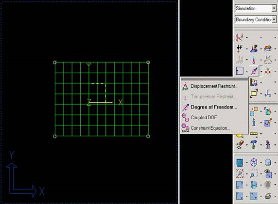
Figure 10.74 Boundary condition
Run program file
Move to Model Solution.
Run program file, ‘RecurDyn_fem.prg’
After you choose the program file, click OK.
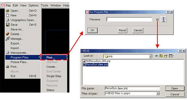
Figure 10.75 Read program file
Enter mode number.
Enter number of modes to extract in I-DEAS Prompt window.
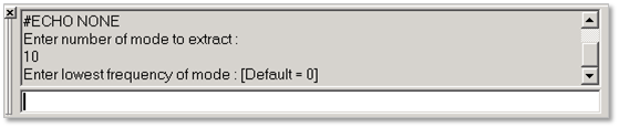
Figure 10.76 Input mode number and lower frequency
Finishing message.
If analysis successfully finished, RecurDyn.unv is generated in working directory.
10.2.4.2.2. CMS Analysis
Figure 10.77 Target model
Run I-DEAS and create model.
Define FE model.
Move to Meshing.
Define Element
Select Define shell mesh.
You can define mesh about plate model in ‘Define mesh’ window. That is, you are able to change element type, element length and etc.
Figure 10.80 Defining mesh
Make a FE entity
Choose meshing method
Generate node and element
After choosing the method, select the part and enter. Then you can see the node and element numbers which are generated (Result information) in the top left side on the working window
Click Yes
If you don’t want to auto mesh, then you can make a node wherever you want and can also generate element with this node
Figure 10.81 Mesh geometry
Define DOF set
Move to Boundary Conditions
Create degree of freedom(DOF) set
Select interface nodes that are connected to a joint or be applied by a force in the flexible body. Specify all six (translational and rotational) DOF for beam or shell elements, but only three (translational) DOF for solid elements.
Figure 10.82 Boundary condition
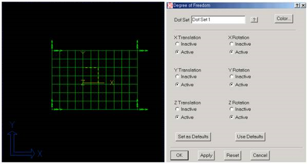
Figure 10.83 Define DOF of interface nodes
Run program file
Move to Model Solution.
Run program file, ‘RecurDyn_cms.prg’
After you choose the program file, click OK.
Figure 10.84 Read program file
Enter mode number.
Enter number of mode to extract in I-DEAS Prompt window.
Figure 10.85 Input mode number and lower frequency
Finishing message.
If analysis successfully finished, Recurdyn.unv is generated in working directory.
Note
The I-DEAS interface is not able to extract global stiffness matrix from I-DEAS. So you cannot use the work related to the stiffness matrix dynamic, such as exporting dynamic correction mode and importing extra modes and so on.