29.5.1.2. Properties
The Beam Belt property page is shown in Figure 29.73. And its parameters are explained below. The user can modify properties for the beam belt such as geometry information, FFlex body characteristics, boundary condition, and output. The general pages such as General Page, Graphic Property Page, Origin and Orientation Page are same with general body.
FE Info (Refer to FEInfo. in FFlex)
Connecting Parameter (Refer to Connecting Parameter in FFlex)
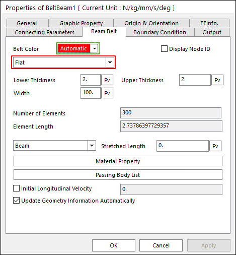
Figure 29.73 Beam Belt property page [Beam Belt page]
Belt Color: Changes the color of belt line.
Display Node ID: If this function is checked, all nodes belong to the displaying belt. And you can see the nodal body information in this mode.
Beam Belt Type: 4 types are supported in RecurDyn/Belt.
Flat: The cross section of belt is rectangular.
V: The cross section of belt is trapezoidal.
Round: The cross section of belt is circular.
Timing: The shape in the X-Z plane is the tooth profile.
Number of Elements: Defines the number of force elements to connect nodes.
Element Length: Defines the length of element.
Stretched Length: Defines the stretched length from the initial length.
Initial length = element length-stretched length
Material Property: Allows you to access the dialog box defining the material property of belt. It is active only in the beam model mode.
Passing Body List: Displays all geometries contacted belts.
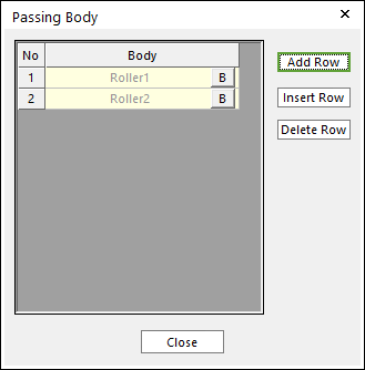
Figure 29.74 Passing Body dialog box
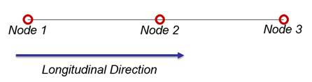
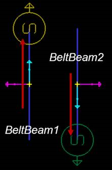
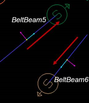
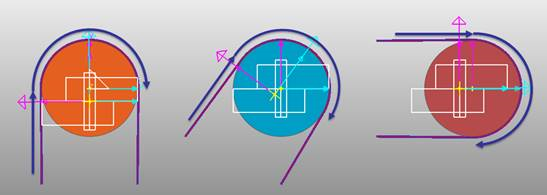
Initial Longitudinal Velocity: Defines the initial velocity in the longitudinal direction of belt. Below figures are present the longitudinal direction about open loop and close loop of belt assembly.
Update Geometry Information Automatically
29.5.1.2.1. Beam Belt Shape
Flat
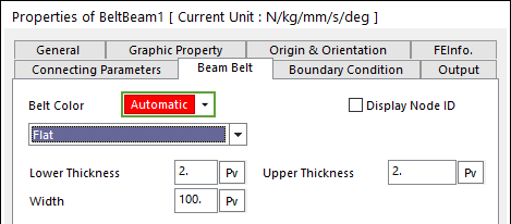
Figure 29.75 Beam Belt property page [Flat shape]
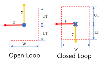
Figure 29.76 Flat Shape geometry
Lower Thickness: Defines the lower thickness of belt.
Upper Thickness: Defines the upper thickness of belt.
Width: Defines the width of belt
V
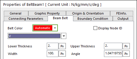
Figure 29.77 Beam Belt property page [V shape]
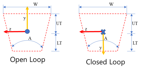
Figure 29.78 V Shape geometry
Lower Thickness: Defines the lower thickness of belt.
Upper Thickness: Defines the upper thickness of belt.
Width: Defines the width of belt
Angle: Defines the angle of belt.
Round
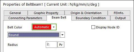
Figure 29.79 Beam Belt property page [Round shape]
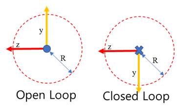
Figure 29.80 Round Shape geometry
Radius: Defines the radius of belt.
Timing
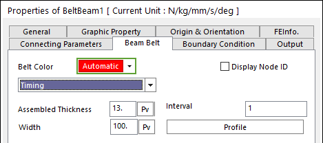
Figure 29.81 Beam Belt property page [Timing shape]
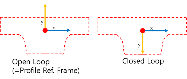
Figure 29.82 Timing Shape geometry
Assembled Thickness: Defines the value used for the assembling timing pulley with the timing shape of beam belt.
Interval: Defines a cycle of node with the tooth profile.
Width : Defines the width of belt
Profile
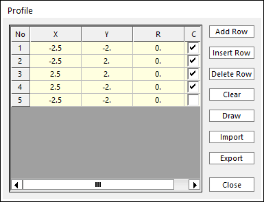
Figure 29.83 Profile dialog box
X, Y, R: Defines points and radius. All data must be defined with respect to the profile marker.
C: Defines whether the point will be used for contact calculations. Default is checked, meaning that contact is considered.
Add Row: Adds a row to the end of the table.
Insert Row: Inserts a row where the cursor is and move the current and later rows down.
Delete Row: Deletes the row where the cursor is and move the later rows up.
Clear: Deletes all rows in the table.
Draw: Shows the defined profile. The user can move points graphically by using the mouse directly.
Import: Imports the X, Y, R and C data pairs from a CSV file or a MAT file or a text file. In the case of the text file, the usage of the comma, the tab, and the space can be the delimiter between the three columns in the file. And when using the Excel file, the user can select the Tab-delimited text file output option or the CSV (Comma-Separated Values) file output option to save the Excel file which can be imported.
Export: Exports the X, Y, R and C data pairs to a CSV file or a MAT file or a text file.
29.5.1.2.2. Material Property
The Material Property dialog box is shown clicking Material Property in the Beam Belt dialog box. And the parameters are explained below.
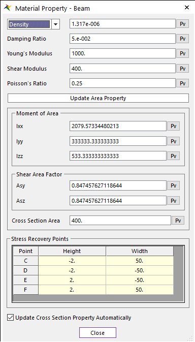
Figure 29.84 Material Property dialog box
Damping Ratio( \(\xi\) ): Defines the damping ratio. It has the structural damping ratio of the belt. The damping matrix of C is computed from the following equation.
\({C} = \xi \cdot {K}\)
Young’s Modulus: Defines the young’s modulus of belt
Shear Modulus: Defines the shear modulus of belt
Poisson’s Ratio: Defines the poisson’s ratio of belt.
Update Area property: Automatically calculate the:
Moment of area
Cross section area: This option is inactive in the V type.
Shear Area Factor (Asy, Asz)
Stress Recovery Points (C,D,E,F)
Ixx, Iyy, Izz: Defines the moment of area of belt.
Shear Area Factor : Defines the shear area factor Asy and Asz.
Cross section area: Defines the cross section area of belt.
Stress Recovery Points : Defines the stress/strain recovery points C,D,E, and F of the FFlex/Beam2 element
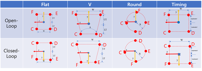
Figure 29.85 Stress Recovery Points C, D, E, and F
Update Cross Section Property Automatically : If this option is checked, property values are updated automatically as geometry data change without clicking Update Area Property.
Note
In order to improve the analysis performance of Timing Belt, the value of Moment of Area and the value of Cross Section Area have to be set as accurately as possible according to belt profile.