9.7.9. Creation
9.7.9.1. Node Creation
The node creation allows the user to define other nodes that are used for the primary node of the FDR element.
There are three ways to define the node position.
You can easily understand how to generate a node in a different way.
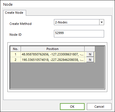
Figure 9.100 Node dialog box
Create Method
Point: Defines the special location directly where the node was created.
2-Nodes: Defines the node position with two different points. If you define these two points in a window, a new node is created in the center of these two points.
3-Nodes: Defines the node position with three different points. (There exists a unique circle that passes the three points.) If you define these three points, a new node is created in the center of the circle that passes the three points.
Node ID: Defines a node ID to the node.
Position: Defines positions to specify the node.
9.7.9.2. Element Creation
One element can be created at a time. Beam2, Shell3, Shell4, Solid4, and Solid8 elements are possible to create.
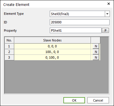
Figure 9.101 Create Element dialog box
Element Type: Selects a type to the element.
ID: Defines an element ID to the element.
Property: Defines the property to the element.
Secondary Nodes: Defines positions of nodes included in the element.
9.7.9.3. FDR Creation
The FDR element is the Force Distributing Rigid element.
There are RigidE type that defines rigid body element like RBE2 element and InterpE type that defines interpolation element like RBE3 in the other FE software.
This element plays a role to transfer force and moment from primary node to secondary nodes.
By using the FDR element in the FE Entity, you can easily create the FDR element by selecting the primary node and secondary nodes.
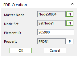
Figure 9.102 FDR Creation dialog box
Type: Selects a type to the FDR element.
Primary Node: Defines a primary node to the FDR element.
Node Set: Defines a node set to the FDR element.
Element ID: Defines an element ID to the FDR element.
Property: Defines the property to the FDR element.
9.7.9.4. Mass Creation
The Mass element is used to represent a lumped mass.
By using the Mass element in the FE Entity, you can easily create the Mass element by selecting the node.
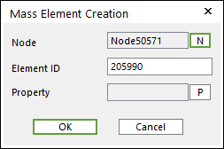
Figure 9.103 Mass Element Creation dialog box
Node: Defines a target node to the Mass element.
Element ID: Defines an element ID to the Mass element.
Property: Defines the property to the Mass element.