30.2.5. Roller Link
A pair of chain link consists of a roller link and pin link. An offset link is used when an odd number of chain links is required. A user must create a pair of chain link from which all chain links are copied. Once a pair of chain links is created, it is registered as clone body. The inertial properties of the assembled chain link are automatically duplicated as the values of clone body. A single pin is used to connect two links of a chain system in this model. The geometric information provided by the user is used for both display and contact force computation in the solver. Therefore, the chain link properties must be defined carefully prior to assembling a chain system.
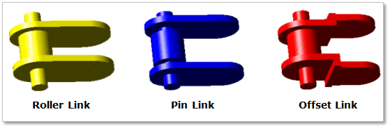
Figure 30.39 Chain link geometry
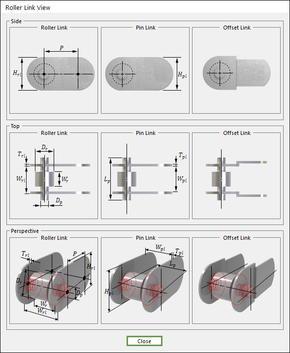
Figure 30.40 Chain link dimension information
P |
Pitch |
Dr |
Roller Diameter |
Wr |
Roller Width |
Wrl |
Width between Roller Link Plate |
Trl |
Thickness of Roller Link Plate |
Hrl |
Height of Roller Link Plate |
Wpl |
Width between Pin Link Plate |
Tpl |
Thickness of Pin Link Plate |
Dp |
Height of Pin Link Plate |
Dp |
Pin Diameter |
Lp |
Pin Length |
30.2.5.1. Modeling Options
The user can create a chain link as follows.
Point, WithDialog
Point: Selects a point on Ground to define the chain link. It doesn’t matter where the chain link is because the created body is a clone body for segment assembly.
WithDialog: Modifies the property for the chain link. The chain link is created with clicking OK.
30.2.5.2. Properties
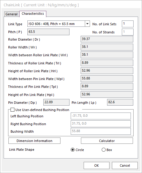
Figure 30.41 Roller Chain Link property page [Characteristics page]
The Roller Chain Link property page is shown in Figure 30.41. The parameters are explained below. In order to understand the geometry, refer to Dimension Information.
Link Type: General Roller Link type and ISO 606 Library type are supported in RecurDyn/Chain. All data can be modified in the case of General Roller Link type.
No. of Link Sets: Generates a link or links as the number of setting links. The user can customize the generated link set using Link Set Customization in Assembly dialog during assembly. Refers to click here.
The user generates from one to five.
The generating links can be edited in the clone body.
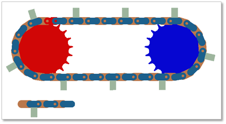
Figure 30.42 Example of 3 link sets
Pitch (P): Enters the pitch
Roller Diameter (Dr): Enters the roller diameter of link.
Roller Width (Wr): Enters the roller width of link.
Width between Roller Link Plate (Wrl): Enters the width between roller link plates.
Thickness of Roller Link Plate (Trl): Enters the thickness of roller link plate.
Height of Roller Link Plate (Hrl): Enters the height of roller link plate.
Width between Pin Link Plate (Wpl): Enters the width between pin link plates.
Thickness of Pin Link Plate (Tpl): Enters the thickness of pin link plate.
Height of Pin Link Plate (Hpl): Enters the height of pin link plate.
Pin Diameter (Dp): Enters the pin diameter of link.
Pin Length (Lp): Enters the pin length of link.
Use User-defined Bushing Position: If it is checked, Bushing force can be defined on different position with pin position.
Left Bushing Position: Defines a base marker position of Bushing force.
Right Bushing Position: Defines an action marker position of Bushing force.
Bushing Width: Defines a width between two bushing forces.
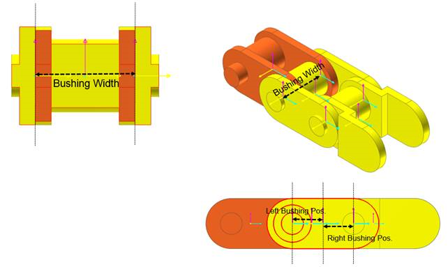
Figure 30.43 Dimension information of user-defined bushing position
Dimension Information: Shows dimension information of the geometry for Roller Link.
Calculator: It is useful for finding specific value to define the relation of between sprockets and chain links.
Link Plate Shape: Choose Link Plate Shape as a circle or a box. It changes the mass and inertia of chain link. Chain Link Plate Contact Shape is applied in Assembly proprty page independently.