29.8.4. Tension Sensor
This sensor is to measure the tension of the belt segment. The belt segment passes the range of tension sensor and is the nearest to tension sensor.
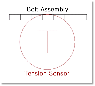
Figure 29.106 Tension Sensor
\(\mathbf{A}_{e} \equiv \begin{bmatrix} \mathbf{f}_{e} & \mathbf{g}_{e} & \mathbf{h}_{e} \\ \end{bmatrix}\)
\(\mathbf{A}_{t} \equiv \begin{bmatrix} \mathbf{f}_{t} & \mathbf{g}_{t} & \mathbf{h}_{t} \\ \end{bmatrix}\)
\(\begin{pmatrix} \mathbf{g}_{c} = \mathbf{g}_{e} \\ \mathbf{f}_{c} = \mathbf{g}_{c} \times \mathbf{h}_{t} \\ \mathbf{h}_{c} = \mathbf{g}_{c} \times \mathbf{f}_{c} \\ \end{pmatrix}\)
\(\mathbf{A}_{c} \equiv \begin{bmatrix} \mathbf{f}_{c} & \mathbf{g}_{c} & \mathbf{h}_{c} \\ \end{bmatrix}\)
\(\mathbf{\sigma}_{c}^{'} = \mathbf{A}_{c}^{T}\mathbf{\sigma}_{c}\mathbf{A}_{c}\)
\(\mathbf{\sigma}_{c}^{'} = \begin{bmatrix} \sigma_{\text{xx}}^{'} & \sigma_{\text{xy}}^{'} & \sigma_{\text{xz}}^{'} \\ \sigma_{\text{yx}}^{'} & \sigma_{\text{yy}}^{'} & \sigma_{\text{yz}}^{'} \\ \sigma_{\text{zx}}^{'} & \sigma_{\text{zy}}^{'} & \sigma_{\text{zz}}^{'} \\ \end{bmatrix}\)
\(\sigma_{o} = \sigma_{\text{xx}}^{'}\)
- where,
- \(\sigma_{o}\) is a stress value and the result of sensor\(\mathbf{\sigma}_{c}^{'}\) is the local stress tensor of the closet position of Element in the range of the sensor.\(\mathbf{\sigma}_{c}\) is the global stress tensor of the closet position of Element in the range of the sensor. In the case of shell type element, \(\mathbf{\sigma}_{c}\) is the mid-stress acting on the neutral surface.\(\mathbf{A}_{c}\) is the reference frame of the output of the sensor. The x axis of \(\mathbf{A}_{c}\) is an expecting direction vector for acting a tension force.\(\mathbf{A}_{t}\) is the reference frame of the sensor. The z axis of \(\mathbf{A}_{t}\) is the normal direction vector of the tension force.\(\mathbf{A}_{e}\) is the reference frame of the closet position of Element in the range of the sensor. The y axis of the \(\mathbf{A}_{e}\).
29.8.4.1. Modeling Options
The user can create a tension sensor as follows.
Point, Distance
Point: Selects a point on a body to define the center of tension sensor.
Distance: Defines a range of region to measure output.
Note
The user should define the sensing target entity by using Tension Sensor property page.
Body, Point, Distance
Body: Selects a body to define the parent body of tension sensor.
Point: Selects a point on the assembly to define the center of tension sensor.
Distance: Defines a range of region to measure output.
Note
The user should define the sensing target entity by using Tension Sensor property page.
Assembled Body, Point, Distance
Assembled Body: Selects an assembly as a target entity.
Point: Selects a point on the assembly to define the center of tension sensor.
Distance: Defines a range of region to measure output.
Body, Assembled Body, Point, Distance
Body: Selects a body to define the parent body of tension sensor.
Assembled Body: Selects an assembly as a target entity.
Point: Selects a point on the assembly to define the center of tension sensor.
Distance: Defines a range of region to measure output.
29.8.4.2. Properties
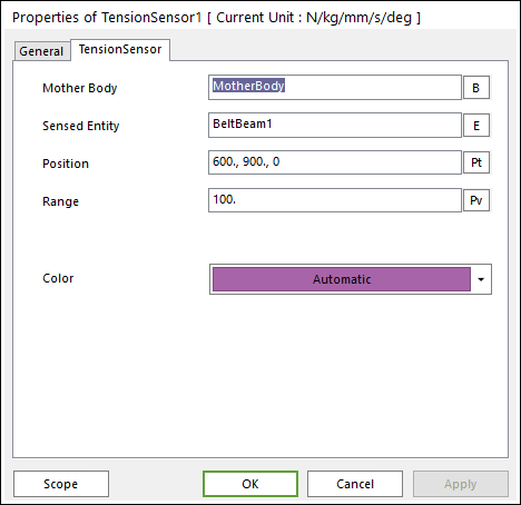
Figure 29.107 Tension Sensor property page
The Tension Sensor property page is shown in Figure 29.107. And its parameters are explained below.
Mother Body: Select the body attached the sensor.
Sensing Entity: Select the assembly of belt system to measure the output.
Position: Enter the center position of sensor.
Range: Enter the range of region to measure the output.
Color: Select the color of sensor.