28.3.4. CAD Center Flange
The basic parameters of CAD center flange are same to the basic parameters of Center Flange provided in Track_LM Toolkit. But, the user should construct a side contact between the Track Link and the CAD center flange. The following steps explains how to create a user-defined CAD center flange.
Step to Create a CAD Center Flange
Import or create a user-defined CAD center flange geometry.
Click the CAD Center icon of the Flange group in the Track (LM) tab
Solid: Selects a desired solid body. (The geometry reference frame of the desired solid must be on the Inertia Marker. Refer to Preparing for CAD Track Entity)
Point: Selects a point where the CAD Center Flange is created.
Define a contact surface for the side contact with the Track Link after creating the CAD Center Flange.
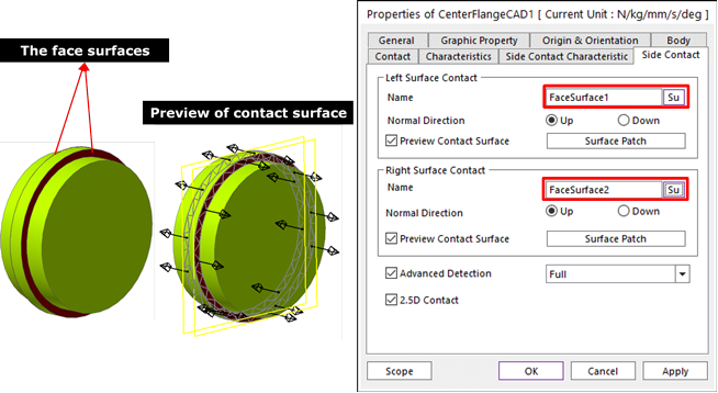
Enter in Body Edit mode.
Create surfaces by using Face Surface. The user can also use other generating surface tools (importing a surface geometry etc…).
Define the contact surfaces in Side Contact page. Refer to Contact Page.
Define the contact characteristic of the Side Contact. Refer to Characteristic Page of Contact.