20.6.9.2. DC
The DC machine block implements a series-connected or a shunt-connected DC motors.
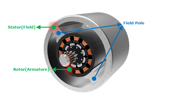
Figure 20.142 DC Motor
Dialog Box
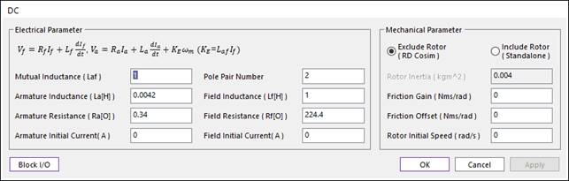
Figure 20.143 DC dialog box
Parameter Name |
Signal |
Description |
Mutual Inductance |
\(K_e\) |
The magnetizing inductance. This is characteristic value of the motor. Please set to ‘1’ when you don`t know the value. [H] |
Pole Pair Number |
The number of pole pairs. It means how many pairs of Field Pole there are. |
|
Armature Resistance |
\(R_a\) |
The armature resistance between the armature terminal A+ and A-. You can find the value of Armature Resistance in the datasheet. [Ohms] |
Armature Inductance |
\(L_a\) |
The armature inductance between the armature terminal A+ and A-. You can find the value of Armature Inductance in the datasheet. [H] |
Armature Initial Current |
Initial value of armature current. Set this value to ‘0’ if you don`t know it. |
|
Field Resistance |
\(R_f\) |
The field resistance between the field terminal F+ and F-. You can find the value of Filed Resistance in the datasheet. [Ohms] |
Field Inductance |
\(L_f\) |
The field inductance between the field terminal F+ and F-. You can find the value of Filed Inductance in the datasheet. [H] |
Field Initial Current |
\(A\) |
Initial field current. Set this value to ‘0’ if you don`t know it. |
ParameterName |
Signal |
Description |
Exclude Rotor/Include Rotor |
Select the type of Motor between Exclude Rotor and Include Rotor. The more detail explanation of two types is in the Equation of PMDC. |
|
Rotor Inertia |
\(J\) |
Inertia of rotor. This parameter don`t need on the Rotor Speed Type. You can find the inertia of rotor in the datasheet. [kg*m^2] |
Friction Gain |
\(B\) |
Viscous friction gain between motor and load. When you apply the friction between the motor and the load in your dynamic model, you have to set this value to ‘0’. [Nms] |
Friction Offset |
\(T_f\) |
Viscous friction Offset between motor and load ( \(B\omega\) + offset). When you apply the friction between the motor and the load in your dynamic model, you have to set this value to ‘0’. [Nm] |
Rotor Initial Speed |
\(\omega\) |
Initial value of rotor speed. Set this value to ‘0’ if you don`t know it. [rad/s] |
20.6.9.2.1. Input and Output of DC
Exclude Rotor (RD Cosim) Type
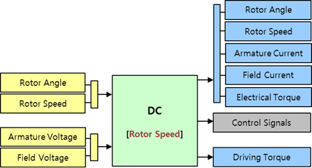
Figure 20.144 Input Port and Output Port of Rotor Speed Type
Port |
Input Signal |
Description |
|
1st Port |
Rotor Angle |
\(\theta\) |
The Rotor Angle. [rad] |
Rotor Speed |
\(\omega\) |
The Rotor Angular Speed. This value is a differential of Rotor Angl. [rad/s] |
|
2nd Port |
Armature Voltage |
\(V_a\) |
The Armature Voltage. [V] |
Field Voltage |
\(V_f\) |
The Field Voltage. [V] |
Port |
Output Signal |
Description |
|
1st Port |
Rotor Angle |
\(\theta\) |
The Rotor Angle. [rad] |
Rotor Speed |
\(\omega\) |
The Rotor Angular Speed. [rad/s] |
|
Armature Current |
\(I_a\) |
The Armature Current. [A] |
|
Field Current |
\(I_f\) |
The Field Current. [A] |
|
Electrical Torque |
\(T_e\) |
The Generated electrical torque. [N.m] |
|
2nd Port |
Control Signals |
This signal is used when you control the motor use the DC Drive block. When you use the DC Machine block, this port does not export any signal. |
|
3rd Port |
Driving Torque |
\(T_d\) |
The driving torque \({{T}_{d}}\) subtracts the viscous friction of rotor from the electrical torque \({{T}_{e}}\). The more detail explanation of this is in the Rotor Speed part of the Equation of PMDC. [N.m] |
Example
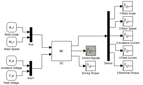
Figure 20.145 Example of Rotor Speed Type
Include Rotor (Standalone) Type
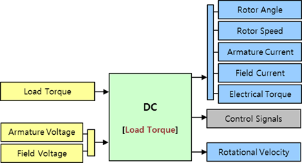
Figure 20.146 Input Port and Output Port of Load Torque Type
Port |
Input Signal |
Description |
|
1st Port |
Load Torque |
\(T_L\) |
The Load Torque. This value is used to calculate the Driving Torque in the Load Torque Type. [N] |
2nd Port |
Armature Voltage |
\(V_a\) |
The Armature Voltage. [V] |
Field Voltage |
\(V_f\) |
The Field Voltage. [V] |
Port |
Output Signal |
Description |
|
1st Port |
Rotor Angle |
\(\theta\) |
The Rotor Angle. [rad] |
Rotor Speed |
\(\omega\) |
The Rotor Angular Speed. [rad/s] |
|
Armature Current |
\(I_a\) |
The Armature Current. [A] |
|
Field Current |
\(I_f\) |
The Field Current. [A] |
|
Electrical Torque |
\(T_e\) |
The Generated electrical torque. [N.m] |
|
2nd Port |
Control Signals |
This signal is used when you control the motor use the DC Driver block. When you use the DC Machine block, this port does not export any signal. |
|
3rd Port |
Rotational Velocity |
Rotor Rotational Velocity. [rad/s] |
Example
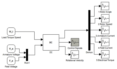
Figure 20.147 Example of Load Torque Type
20.6.9.2.2. Equation of DC
Electrical Part
The voltage equations of DC are as follows.
\(\begin{aligned} & {{V}_{f}}={{R}_{f}}{{I}_{f}}+{{L}_{f}}\frac{d{{I}_{f}}}{dt} \\ & {{V}_{a}}={{R}_{a}}{{I}_{a}}+{{L}_{a}}\frac{d{{I}_{a}}}{dt}+E \\ \end{aligned}\)
- where,
- \({{V}_{f}}\) is the field voltage.\({{R}_{f}}\) is the field resistance.\({{L}_{f}}\) is the field inductance.\({{I}_{f}}\) is the filed current.\({{V}_{a}}\) is the armature voltage.\({{R}_{a}}\) is the armature resistance.\({{L}_{a}}\) is the armature inductance.\({{I}_{a}}\) is the armature current, and E is the back electromotive force.
The field terminal and the armature terminal are separated so that the machine model can be a series-connected or a shunt-connected DC motors. A counter-electromotive force (CEMF), which is generated between the armature terminals, is proportional to the machine speed.
\(E={{K}_{E}}\omega\)
- where,
- \({{K}_{E}}\) is the CEMF constant.\(\omega\) is the angular speed.
The CEMF constant \({{K}_{E}}\) is proportional to the field current \({{I}_{f}}\)
\(K_e=L_{af}I_f\)
- where,
\({{L}_{af}}\) is the field-armature mutual inductance.
The torque, which is developed by DC motor, is proportional to the armature current \({{I}_{a}}\).
\({{T}_{e}}={{K}_{E}}{{I}_{a}}={{K}_{T}}{{I}_{a}}\)
The torque constant \({{K}_{T}}\) is equal to the CEMF constant \({{K}_{E}}\).
When the machine is in generator mode, the sign of torque is positive. In motor mode, the sign of torque is negative.
Mechanical Part
For more information, refer to Equation of PMDC.