9.8.3. Flex Thermal Loads
Flex Thermal Loads generates temperature differences on FFlex bodies. This can be supported to elements with Elastic Isotropic material.
The Node Set:
Should be defined before creating Flex Thermal Loads.
Must belong to a FFlex body.
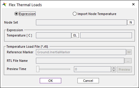
Figure 9.125 Flex Thermal Loads dialog box
Type: There are 2 types to input temperature Expression or Import Node Temperature.
Node Set: Defines a node set.
Expression [ \(^{\circ} C\) ]
Temperature: Defines an expression to the temperature by clicking EL.
Temperature Load File (*.rtl): This group is activated when selecting Import Node Temperature.
Reference Marker: Specifies the Reference Marker to apply the thermal load. The default Reference Marker becomes the Inertia Marker of the ground.
RTL File Name: Enters the RTL file name and its path. To check more information about data type of RTL file, click here.
Preview Time: Preview a contour of imported temperature field at specified preview time.
Contour Preview
In the case contour preview, user can check how nodal temperature data is applied to selected node set.
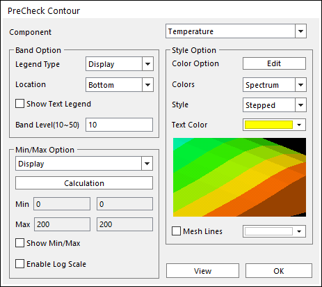
Figure 9.126 PreCheck Contour dialog box
Band Option, Min/Max Option and style option is the same functionalities to the FFlex contour option.
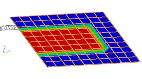
Figure 9.127 Example of contour preview
Concept of the Thermal Coefficient
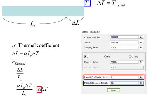
Thermal coefficient [ \(1/^{\circ} C\) ] : The ratio between the original length and stretched length by the temperature. It is the material property.
Thermal Reference Temp [ \(^{\circ} C\) ]: The reference temperature is user-defined value. The difference between current temperature and reference temperature occurs the thermal deformation.