31.1.9. Bevel Gear
A bevel gear is used to transmit power between two intersecting shafts at any angle. It is classified as Straight, Spiral, and Zerol according to checking the Spiral Angle and Cutter Radius option. Straight bevel gears are the simplest form which has straight and tapered teeth. Spiral bevel gears have curved oblique teeth on which contact starts at one end of the tooth and progresses smoothly to the other end. And then, Spiral bevel gears have two or more teeth in contact at all times such that they transmit motion more smoothly and quietly than Straight bevel gears. Finally, Zerol bevel gears are similar to Spiral bevel gear, but it has been defined the spiral angle as zero at the middle of the face width. Therefore, the direction of the curved teeth of it is the same general direction as Straight bevel gears.
The following figure shows three types of bevel gears generated in RecurDyn/Gear.
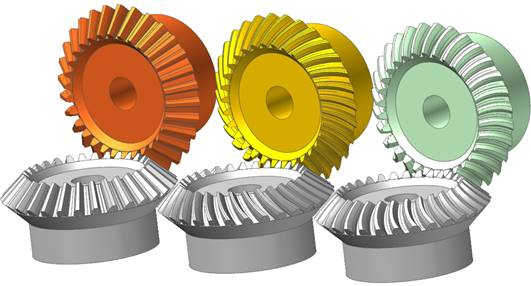
Figure 31.47 Types of Bevel Gears (Straight, Spiral, Zerol)
A bevel gear is composed of a single body. Gear geometries are created from the parameters of ISO standards. The tooth profile is represented by multiple arcs. The sprocket tooth geometry data is:
Created from a predefined data file
Edited from a predefined data file
Exported from a predefined data file
Imported from a predefined data file
Terminology
Bear gear teeth are proportioned in accordance with the standard system of tooth proportion s used for spur gears. However, because bevel gear teeth are tapered and the narrow end of the teeth vanishes at the center of gear geometry, the reference of important parameter dimension is the outer end as shown Figure 31.48.
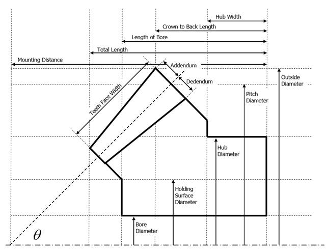
Figure 31.48 Bevel Gear Geometry
For more information, refer to Geometric Entities.
31.1.9.1. Properties
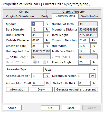
Figure 31.49 Bevel Gear property page [Geometry Data page]
The Bevel Gear property page is shown in Figure 31.49. The parameters are explained below.
Module: Enters the module of the gear.
Number of Teeth: Enters the number of teeth. The maximum number of teeth of gear is 400.
Bore Diameter: Enters the bore diameter of bevel gear.
Hub Diameter: Enters the hub diameter of bevel gear.
Outside Diameter: Enters the outside diameter of bevel gear.
Mounting Distance: Shows the mounting distance of bevel gear.
Total Length: Shows the total length of bevel gear.
Length of Bore: Enters the length of bore for bevel gear.
Crown to Back Len.: Enters the crown back length of bevel gear.
Hub Width: Enters the hub width of bevel gear.
Holding Surf. Dia.: Shows the holding surface diameter of bevel gear.
Teeth Face Width: Enters the width of teeth face for bevel gear.
Spiral: In the current RecurDyn, this function is not supported.
Pressure Angle: Enters the pressure angle of the gear.
Parameter Type: two methods are supported to define the Addendum and Dedendum.
Factor: Defines the addendum and dedendum as factors. For more information, click here.
Addendum Factor: Enters the factor to define the addendum.
Dedendum Factor: Enters the factor to define the dedendum.
Addendum Radius & Whole Depth: Defines the addendum and dedendum as addendum radius and whole depth. For more information, click here.
Addendum Radius: Enters the addendum radius for the gear.
Whole Depth: Enters the whole depth as summation for the addendum and dedendum.
Adden. Mod. Coeff.: Enters the coefficient to define the addendum.
Delta Tooth Thick.: Enters the delta value to define the tooth thickness. For more information, click here.
Information: Shows the calculated values for Pitch Radius, Tip Radius, Base Radius, Root Radius, and Circular Tooth Thickness.
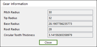
Figure 31.50 Gear Information dialog box
Draw: All data must be defined with respect to the tooth marker. You can move points graphically by using the mouse directly.
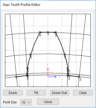
Figure 31.51 Gear Tooth Profile Editor dialog box
Generate optimal arc segment: In order to apply the modification of tooth, this button should be clicked.