33.3.2. Piston Liner Connector
A piston liner connector is defined with two bodies. This entity is created between a cylinder (an engine block) and a piston.
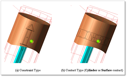
Figure 33.56 Piston Liner Connector
33.3.2.1. Modeling Options
Click the Liner icon of the Piston Connector group in the Piston tab. The user can see the Crank Component Line Connector – Line Connector dialog box.
The user can choose the following types in Component Type and select the position where the constraint bearing is created in Component Index.
Constraint
Cylinder Contact
Surface Contact
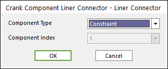
Figure 33.57 Crank Component Liner Connector – Liner Connector dialog box
Click OK.
33.3.2.2. Properties
The user can create the two kinds of liner connectors.
The first one is translational joint
The other is contact liner connector (Cylinder or Surface contact).
33.3.2.2.1. Constraint Type of Linear connector
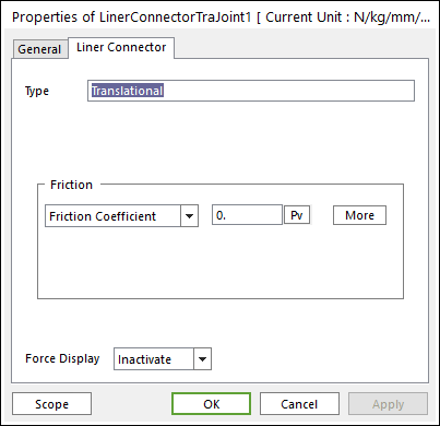
Figure 33.58 Liner Connector property page [Translational Joint]
Please refer to Type of Friction in below.
Standard Friction
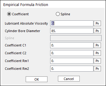
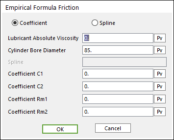
Empirical Formula
33.3.2.2.2. Cylinder Contact Type of Liner Connector
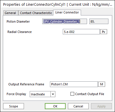
Figure 33.61 Liner Connector property page [Cylinder In Cylinder Contact]
Output Reference Frame: The user can choose another desired Reference Marker.
Contact Output File: If it is checked, the user can get specific output information file such as:
Bodies’ position
Orientation
Contact position
Normal force
Friction force
The user can see the output file in your working folder where your model is in. The output file name is Filename_ContactElementName.out.
Radial Clearance: Defines as a gap between the cylinder and piston.
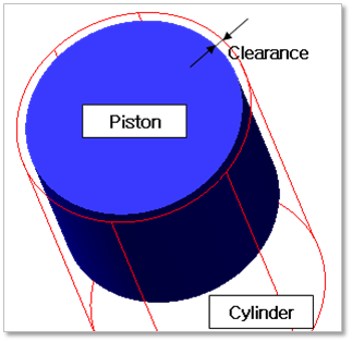
Figure 33.62 Definition of Clearance
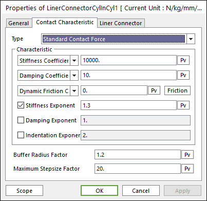
Figure 33.63 Contact Characteristic property page [Cylinder In Cylinder Contact]
Please refer to Type of Friction in below.
Standard Friction
Select Friction Coefficient in the combo box.
Click More and then enter values to define Coulomb Friction. For more information, click here.
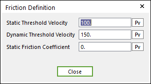
Figure 33.64 Coulomb Friction dialog box
Empirical Formula
33.3.2.2.3. Surface Contact Type of Liner Connector
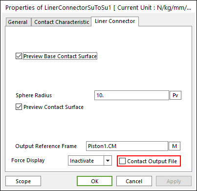
Figure 33.66 Liner Connector property page [Surface To Surface Contact]
Output Reference Frame: The user can choose another desired Reference Marker.
Contact Output File: If it is checked, the user can get specific output information file such as:
Bodies’ position
Orientation
Contact position
Normal force
Friction force
The user can see the output file in your working folder where your model is in. The output file name is Filename_ContactElementName.out.
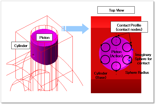
Figure 33.67 Properties of Surface Contact liner connector
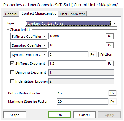
Figure 33.68 Contact Characteristic dialog box [Surface To Surface Contact]
Please refer to Type of Friction in below.
Standard Friction
Select Friction Coefficient in combo box.
Click More and then enter values to define Coulomb Friction. For more information, click here.
Figure 33.69 Coulomb Friction dialog box
Empirical Formula