9.7.8. Display
The Display option controls which Components & Sets are displayed.
The Display of components and sets are controlled by each associated check box.
You can also change the color of any of the groups using the Change Color command on the popup menu that appears when the:
Mouse button is right-clicked.
Cursor is over the group name.
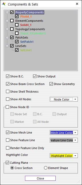
Figure 9.94 Components & Sets dialog box
Show B.C.: Displays boundary conditions.
Show Output: Displays outputs.
Show Beam Cross Section: Display the cross section of Beam Elements.
Show Geometry: Display the Geometry. This option is shown in Mesh Mode.
Show Shell Thickness: Display the thickness of Shell Elements.
Show All Nodes: Displays all node. (It’s useful for beam elements.)
Show Node ID: Displays the Node ID of Node Set, BC, Output, Marker, or All Nodes.
Show Mesh Line: Displays mesh lines in the Shade mode in Rendering Mode.
Show Feature Line: Display the edge line made from the mesh information.
Render Feature Line Only: If the user checks this option, the feature line is displayed only without mesh lines. It is effective to the handling of the working window in case of the big FFlex body.
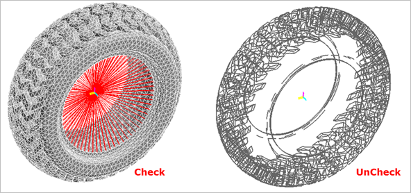
Figure 9.95 Render Feature Line Only
Highlight Color
If Select Element is selected in the Choose Entity Type Toolbar, then the element becomes highlighted by moving the mouse cursor.
The highlighted element is displayed with the highlighted color.
Node Color
The nodes of the body are displayed with this color.
Cutting Plane
If this option is checked, the cross section of the flexible body is displayed.
Cross Section: The cross section of the flexible body is displayed.
Element Shape: The shape of elements in cutting plane are displayed.
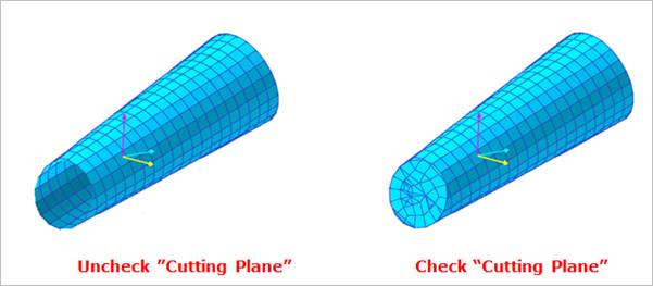
Figure 9.96 Cutting Plane
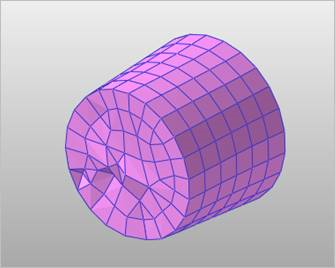
Figure 9.97 Element Shape option in Cutting Plane
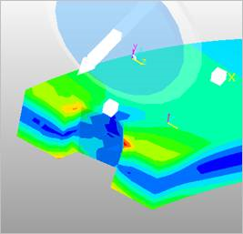
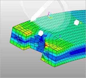
Figure 9.98 Cross Section Contour with Cutting Plane
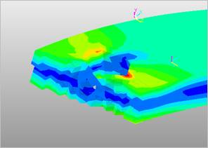
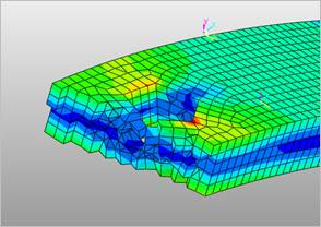
Figure 9.99 Cross Section Contour with Cutting Plane (Element Shape type)