40.4.2. Properties
The user can modify the property using the MMS Type D property page.
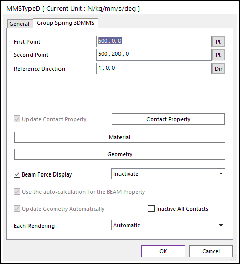
Figure 40.40 MMS Type D property page
First Point: Defines the point you clicked primary. The button part of spring is defined on this point.
Second Point: Defines the point you clicked secondary. The top part of spring is defined on this point.
Reference Direction: Indicates the Geometric Starting point of MMS Type D. Please refer to a below figure.
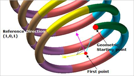
Figure 40.41 Reference Direction
Update Contact Property: If this option is unchecked, the user wants to control each of the contact entities that make up the spring.
Contact Property: The contact forces between upper helix and lower helix of the spring are automatically created using these contact properties. The contact entity between upper helix and lower helix of the spring are defined using “Sphere To Torus Contact”. The geometry for contact is defined internally. The base geometry, torus is defined on lower helix and the action geometry, sphere is defined on upper helix like as a below figure.
Inactive All Contacts: If this option is checked, All Sphere To Torus Contact entities are inactivated.
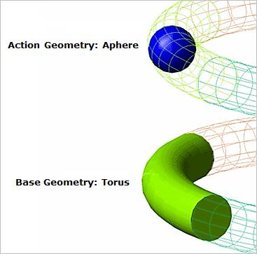
Figure 40.42 Contact between up and lower helix
Material: The total mass can be defined for spring. Young’s modulus, poisson’s ratio, shear modulus, and damping ratio can be defined for Beam forces.
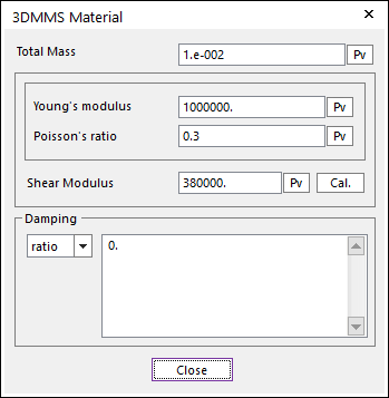
Figure 40.43 3DMMS Material dialog box
Total Mass: Defines the total mass of spring. The density of each multi-mass body of spring is calculated using this Total Mass. Body properties of each multi-mass body of spring are automatically calculated like as follow.
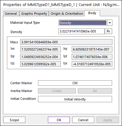
Figure 40.44 Body Properties of a mass of 3DMMS
Young’s modulus: Specify the young’s modulus of elasticity for the beam material.
Poisson’s ratio: Specify the poisson’s ratio.
Shear Modulus: Specify the shear modulus of the beam.
Geometry: Defines the geometry for spring. For more information, click here.
Beam Force Display: Graphically displays the resultant force vector on Working Window.
Use the auto-calculation for BEAM Property: The undeformed length and beam properties from the area are automatically calculated using geometry properties of spring.
Update Geometry Automatically: If this option is unchecked, the position and orientation of the geometry constituting the group are not updated depending on variables in the property page. So, after executing Extract function, this option is unchecked.
Each Rendering: The selected mode can be displayed in Each Render mode.