32.1.1.1. Cylinder Layout
In Cylinder Layout, the user can modify the values to organize the configuration about cylinders and a crank shaft.
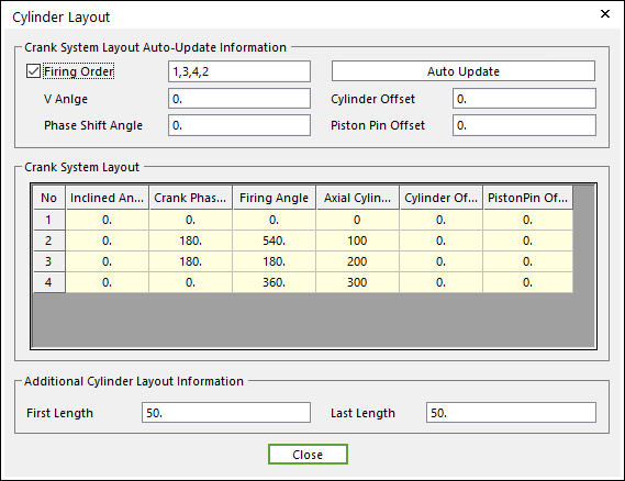
Figure 32.16 Cylinder Layout dialog box
Firing Order: Defines a sequence of cylinder they are fired.
V-angle: Defines an angle of between cylinders. It is a value for v-type and horizontal type engine.
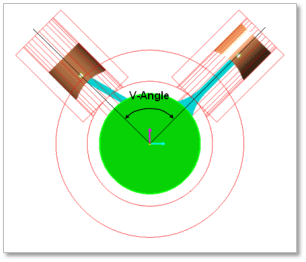
Figure 32.17 V-angle
Phase Shift Angel is valid for V-type.
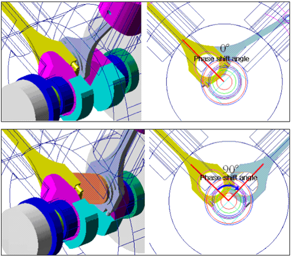
Figure 32.18 Phase Shift Angle
Cylinder Offset & Piston Pin Offset
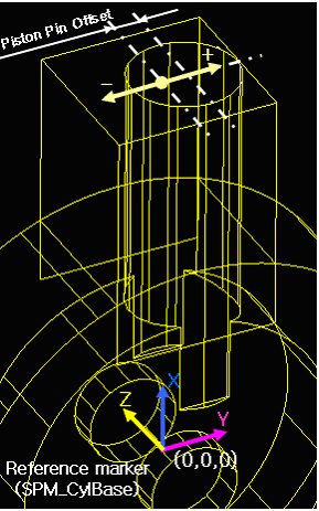
Figure 32.19 Cylinder offset
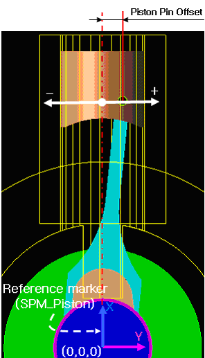
Figure 32.20 Piston pin offset
Inclined Angle is defined by the v-angle and the cylinder number.
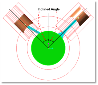
Figure 32.21 Inclined Angle
Crank Phase Angle: Enter the angular distance between the secondary axis of crank system and the position of the crank pin body. For common engine type, it is automatically calculated from the firing order. If the user wants to give the offset value on a cylinder, modify the crank phase angle on the base of the calculated angle.
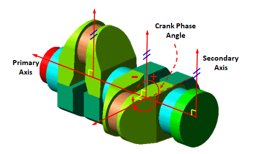
Figure 32.22 Crank Phase Angle
Firing Angle: Defines gas force profiles. When a crank shaft is rotated, a gas force acting on a piston is defined by the gas force profile. When the Crank Shaft Angle corresponds with the firing Angle, the concentrated gas force is occurred around Firing Angle (ex. 540 degree, Figure 32.23). For example, when Crank Shaft Angle is 540 dgree, the concentrated gas force is generated in cylinder No 2.
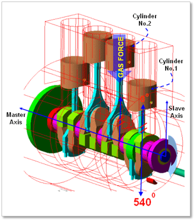
Figure 32.23 An example of Firing Angle of Cylinder No.2 (CW)
Axial Cylinder Distance: Enter the axial cylinder distance from the first cylinder.
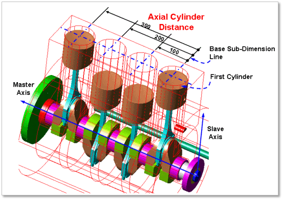
Figure 32.24 Axial Cylinder Distance
Additional Cylinder Layout Information
The first length is the distance between the center point of first main body and first cylinder.
The last length is the distance between the center point of last main body and last cylinder.
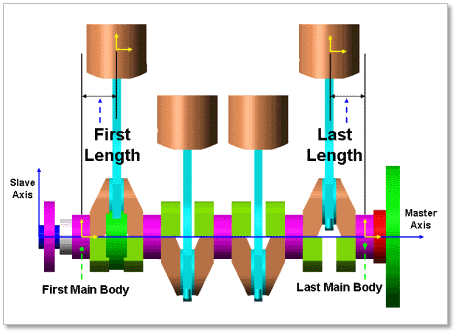
Figure 32.25 First Length & Last Length
32.1.1.1.1. An example of calculation procedure of Cylinder Layout Parameters
Variables Definition
Table 32.1 Variable definition Name of Variable
Definition
Index “i”
Index for the CN-ordered table (upper table index). Base index is 1
Index “j”
Index for the FSi-ordered table (upper table index). Base index is 1
iTCN
Total Number of Cylinder (6)
dVAngle
V-angle (60.0)
dPSA
Phase shift angle (-60.0)
dRF
Rotation Factor (1.0 for CW and -1.0 for CCW)
dTCA
Total Cycle Angle (720.0 for 4 stroke and 360.0 for 2 stroke)
CN[ ]
Array for the Cylinder Number
FO[ ]
Array for the Firing Order
FSN[ ]
Array for the Firing Sequence Number
IA[ ]
Array for the Inclined Angle
EIA[ ]
Array for the Equivalent Interval Angle
CPA[ ]
Array for the Crank Phase Angle
RCPA[ ]
Array for the Relative Crank Phase Angle
FI[ ]
Array for the Firing Interval
FA[ ]
Array for the Firing Angle
Input Data
Engine Type: V-Type
Rotation Type: CW
Cycle Type: 4 stroke
Total Number of Cylinder: 6
V-Angle: 60 degree
Phase shift angle: -60 degree
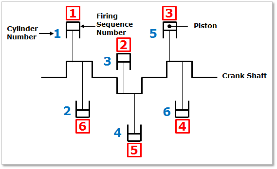
Figure 32.26 Simplified model of Crank system
Calculation Algorithm
IA[i] :(1-2*MOD(CN[i],2))*dVAngle/2.0
EIA[i] : (FSN[i]-1)*dTCA/iTCN
CPA[i] : MOD((IA[i]-EIA[i]*dRF),dTCA) : for only V-type odd number cylinder
CPA[ i ] : MOD((IA[i-1]-EIA[i-1]*dRF)+dPSA),dTCA) : for only V-type even number cylinder
*.CPA[i] : MOD((IA[i]-EIA[i]*dRF),dTCA) : for non V-type engine / for all cylinder
RCPA[i] : MOD(CPA[i]-CPA[1], dTCA) : except for the case of “i=1”, RCPA[1] =0.0
FI[j] : MOD((IA[j]-IA[j-1])-(RCPA[j]-RCPA[j-1])).360.0) : except for the case of “j=1” , FI[1]=0.0
FA[j] : FI[j] + FA[j-1] : except for the case of “j=1”, FA[1] = 0.0
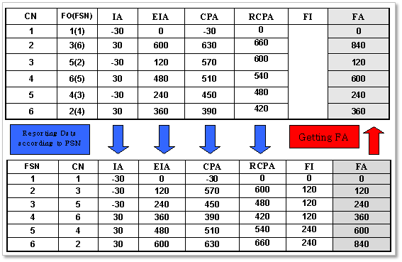
Figure 32.27 Calculation procedure
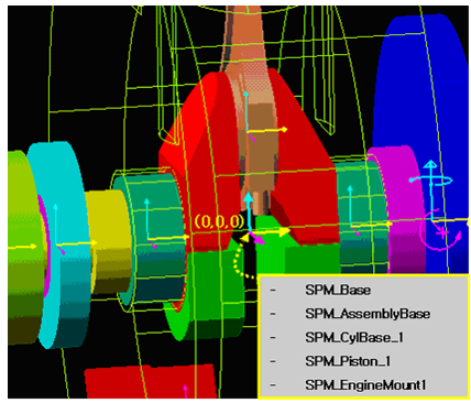
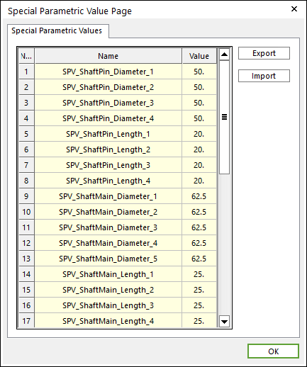
If all data is confirmed, special parametric markers and special parametric values are automatically created according to the global data. Each parametric marker represents the global position of each part and control the origin and direction of each part.
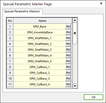
The parametric marker is parameterized by parents-child relationship. For example, SPM_AssebmlyBase is the parent parametric marker of SPM_CylBase_i. So, if SPM_AssemblyBase is moved, SPM_CylBase_i is moved together because the parent marker is moved. In same way, SPM_ShaftPin_i is also moved.It can be checked at SPM menu and SPV menu in Parameter group in the Crank tab.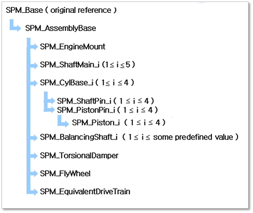
Figure 32.28 Parameterization of Special Parametric Marker (in case of Straight 4 Cylinder Type)
SPM_Base: Represents the whole base of crank-system. It cannot be modified.
SPM_AssemblyBase: Represents the whole control marker of crank-system. If it is moved, the whole crank system is moved.
SPM_EngineMount: Represents the position of Engine Mount.
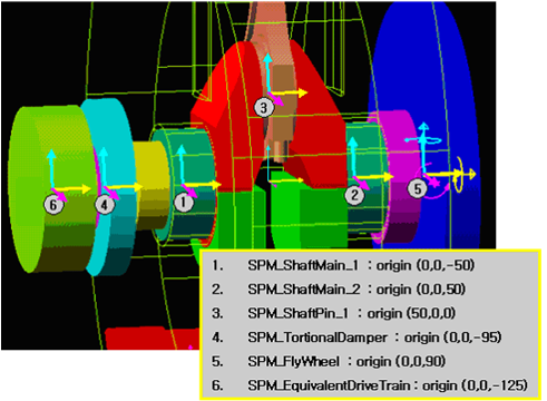
SPM_ShaftMain_i: Represents the position of crankshaft main body.
SPM_CylBase_i: Represents the position of each cylinder. It is affected by the included angle of cylinder and the axial cylinder distance.
SPM_ShaftPin_i: Represents the position of crankshaft pin body. It is affected by the included angle, the crank phase angle and, the axial cylinder distance.
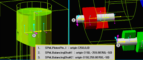
SPM_PistonPin_i: Represents the position of crankshaft main body.
SPM_Piston_i: Represents the position of piston pin.
SPM_BalancingShaft_i: Represents the position of balancing shaft.
SPM_TorisonalDamper: Represents the position of Torsional damper.
SPM_FlyWheel: Represents the position of fly wheel.
SPM_EquivalentDriveTrain: Represents the position of EDT.