6.1.4.2.6. Edge Curve
It allows the user to create curves directly from the created geometry such as a curve, a surface, and a solid geometry. For references, the extracted edge curves can be used for serval functions such as Cam2D Contact, Geo Curve Contact, PTCV Joint, CVCV Joint, and so on.
6.1.4.2.6.1. Modeling Options
The user can create a curve geometry by the following procedure.
Edge
Edge: Select an edge of a body.
MultiEdge
MultiEdge: Selects several edges without selecting a geometry. All edges in Body Edit Mode can be selected.
Solid(Sheet, Wire), MultiEdge
Solid(Sheet, Wire): Selects a solid, surface, or curve geometry. And then the EdgeCurve Operation dialog box appears.
MultiEdge: Selects several edges of the selected geometry.
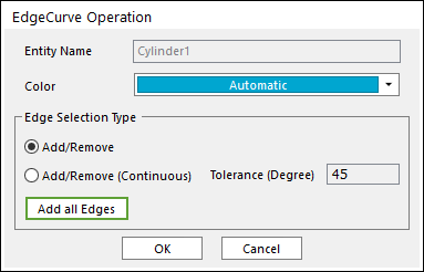
Figure 6.56 EdgeCurve Operation dialog box
Entity Name: Shows the name of the selected entity.
Color: Select a color for the created curve.
Add/Remove: Selects several edges of the selected entity as the user wants to add or remove.
Add/Remove (Continuous): When an edge is selected, all of the connected edges within the user-defined tolerance angle are selected at the same time.
Add all Edges: Adds all edges of the selected entity.
6.1.4.2.6.2. Properties
The user can modify the curve data on the Edge Curve Geometry Property page.
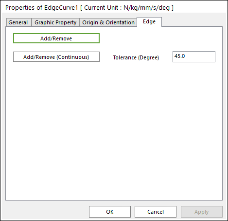
Figure 6.57 Edge Curve property page
Add/Remove: Modifies the edge data. To finish selecting edges, click the empty space with the right mouse button and choose Finish Operation on right-click menu.
Add/Remove (Continuous): When an edge is selected, all of the connected edges within the user-defined tolerance angle are selected at the same time.