6.4.1.3.1. Appendix I Modification Rules for the Solid Contact - Detailed Contact Options
PART I: Modification Rules for the General Cases
The following rules can be useful in many cases when the user encounter any problems with RecurDyn Solid Contact.
General Rules 1. Action/Base Change Rules
Rule 1: A fixed body (if available) should be selected as the base geometry.
Rule 2: The body with the least unconstrained motion should be selected as the base geometry.** The variation of the position and orientation of the base body is smaller than the motion of the action body. For example, a body which is constrained by a motion driver (or many constraints) has some advantages if it is selected as the base geometry in the solid contact. In other words, a body which has the lower number of unconstrained degrees of freedom should be selected as the base geometry.
Rule 3: The bigger body should be selected as the base geometry.** Relatively large geometry should be selected as a base geometry.
Examples
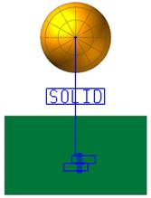
Fixed body: Select the Box as the Base Geometry. The Box is fixed by a fixed joint. Therefore box is more stable than sphere.
Additional Comments: Even if the user selects the sphere as a base geometry, basically there is no problem. But in some special cases, this recommendation provides the better performance and accuracy.

The body which moves less: Select the Blue Cam as a Base Geometry. The cam-like geometry is constrained by a revolute joint and a motion driver is applied. Therefore the cam-like geometry is more stable Additional Comments: Even if a motion driver is applied to a body, if the motion driver is very complex, it can make the body unstable. Generally it is better to choose the body which shows the lesser movement as the Base Geometry.
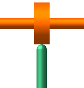
The bigger body: Select the large Blue box as a Base Geometry. The facet size of large geometry is larger than small geometry generally. And the motion variation of large mass is less than small mass geometry in dynamic analysis. Therefore the larger geometry is more stable in the dynamic solution.
General Rules 2. Faceting Rules
The default plane tolerance factor of RecurDyn solid contact is 3, which results in reasonable facets for most contact problems. Consider the following for increased solution accuracy.
Rule 1: Plane tolerance factor for the relatively small geometry is recommended as 4 or 5.
Rule 2: Plane tolerance factor for the relatively large geometry is recommended as 2 or 1.
Examples
|
Recommendations: The Orange (Upper) Geometry is larger than Green (Lower) Geometry. Usually, the facet size of larger geometry is larger than small geometry. Therefore, 1) For more accuracy, decrease the plane tolerance factor of the larger geometry. 2) For faster simulations, increase the plane tolerance factor of the smaller geometry. Additional Comments: RecurDyn suggests that a plane tolerance factor between 1 and 5 be used in RD solid contact. |
|
Recommendations: Generally Sphere-like geometry (Blue geometry) has many facets and Cylinder-like geometry (Purple geometry) has fewer facets. Therefore, increase the plane tolerance factor of sphere-like geometry and decrease the plane tolerance factor of cylinder-like geometry. |

General Rules 3. Bad Contact Result
When a contact is failed or a contact result is not good when using the default values, please try the following rules.
Rule 1: Try to apply the Rule1 For Action Base Change first.
Rule 2: Try Manual Mode (Direct GMP and LMP) such as PART II.
Rule 3: Check mass property. If the mass is too heavy (greater than 100 kg), increase the K and C. And, if the mass is too light(less than 0.01 kg), decrease the K and C. But if there exists other large force such as spring force or axial force, this rule can help the user or not.
Rule 4: Check the model configuration and change other contact parameters. This rule is recommended only for expert user.
Rule 5: Change the Integrator Parameters such as Maximum Time Step, Initial Time Step and Error Tolerance.
PART II. Modification Rules for the Special Cases
CASE I. Tight Concave-Convex Contact Problems
Tight Concave-Convex Contact problems are those problems where the surfaces in the contact region resemble the figure:

This kind of contact problem is very difficult to solve. Therefore if the results or performance is not good in the Tight Concave-Convex contact problems, try the guideline in the following procedures (Following is recommending guideline and is very helpful to understand the Manual Mode of RecurDyn solid contact).
Guideline 1. Use Automatic Option (This is a default option of the solid contact)
Guideline 2. If the user cannot get the good result by Guideline 1, please use Detailed Contact Option.
Change to Manual Mode for the GMP and LMP with Default Values.
Guideline 3. If the user cannot get the good result by Guideline 1 and Guideline 2, please try to change the LMP Value.
Increase the LMP Value (multiply the default LMP by the factor, 1.5 or 2.0)
Decrease the LMP Value (multiply the default LMP by the factor, 0.7 or 0.5)
Increase/Decrease the GMP value in the similar manner can improve the result.
Guideline 4. If the user cannot get the good result by Guideline 1, Guideline 2 and Guideline 3, and if the friction of the contact is OFF, then please try to change the friction to ON. Friction can increase the stability of the contact model. When the user changes the friction to ON, please retry the first three guidelines again.
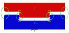
Guideline 5. If the user still cannot get the reasonable solution, please try to change the model as shown in the figure. And please notice that 4 edges of yellow rectangle boxes are not rounded. If these 4 edges are rounded, this contact problem is still the tight concave-convex contact problem”. (This approach is to avoid the tight concave-convex contact problem: This kind of process helps for the good solution in most cases.)
Example for Tight Concave-Convex Contact Problem
Let’s consider this problem with following RecurDyn model. This example case is very difficult one. With the default values, this case cannot be solved. So we follows the guidelines which were explained above.
Model Definitions
..image:: media/image459.png
Bodies: Base Body is Blue (Lower), Action Body is Red (Upper).
Joint : Fixed Joint at Base Body Contact: Between Base and Action Bodies.
Gravity exists.
Solving parameters are all default if not specified.
>> Default GMP = 147.
>> Default LMP = 36.8
We checks the displacement of the action body (red). We expect that the red body falls a little and after contacts, it does not fall further. So, the expected result is shown in the Figure:
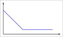
Figure 6.298 Expected result
Guideline 1. Use Automatic Option (This is a Default Option)
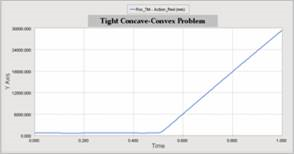
Figure 6.299 Result of the Guideline 1
Comments> The result is unreasonable. The action body bounced off at about 0.5 s. Go to the Guideline 2.
Guideline 2. Change to Manual Mode for the GMP and LMP with Default Values. Result with GMP = 147. , LMP = 36.8 (These are Default Values)
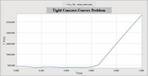
Figure 6.300 Result with the Guideline 2
Comments> The result is better than the result of Guideline 1 but still unreasonable. Go to the Guideline 3.
Guideline 3. Change the LMP Values
Increase the LMP Value with factor 1.5 or 2.0
Decrease the LMP Value with factor 0.7 or 0.5
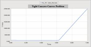
Figure 6.301 Result with LMP = 73.6 (36.8x2)
Comments> The result get worse with the bigger LMP. So we tried the less LMP
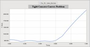
Figure 6.302 Result with LMP = 18.4 (36.8x0.5)
Comments> The result get improved a little. But the result is still unreasonable. Therefore go to the Guideline 4. (Before going to Guideline 4, the user can also try for the GMP value change)
Guideline 4. Since the friction is OFF in this model, we use the Friction ON.
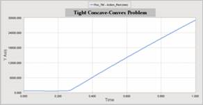
Figure 6.303 Result with default Friction and Guideline 1 (Automatic Mode)
Comments> The result is not good. And we can know that in case of ‘tight concave-convex problem’, using ‘manual mode’ is usually better. Therefore, let’s use manual mode with Friction.
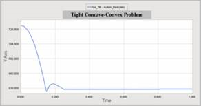
Figure 6.304 Result with Default Friction and Guideline 2(Manual Mode with default LMP&GMP)
Comments> Now, The result is reasonable!
CASE II: Wide Surface Contact Problems
Wide surface means that the surface area in contact region is wide or large.
As the user already noticed out, the Tight Concave-Convex Contact Problem is a special case of the Wide Surface Contact Problems. Therefore the guidelines for the Tight Concave-Convex Contact Problem explained above can be used in Wide Surface Contact Problems similarly. (We don’t include the example case for case II because it is almost similar to the case I).