6.2.2.3. Cylindrical
A cylindrical joint allows both rotation and translation based on the z-axis of the marker. It has one rotational degree of freedom at the direction of the z-axis and one translational degree of freedom along the z-axis. It can be located anywhere along the axis about which the parts can rotate or slide with respect to each other. The orientation of the cylindrical joint defines the direction of the axis about which the parts can rotate or slide along with respect to each other. The rotational axis of the cylindrical joint is parallel to the orientation vector. It passes through the location.
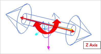
Figure 6.159 Cylindrical Joint icon on Working Window
6.2.2.3.1. Modeling Options
The user can create a joint entity as follows.
Point, Direction
Point: Selects a point on two bodies to define the location of the cylindrical joint.
Direction: Defines the z-axis of rotation and translation.
Body, Body, Point, Direction
Body: Selects a base body of the cylindrical joint.
Body: Selects an action body of the cylindrical joint.
Point: Selects a point to define the location of the cylindrical joint.
Direction: Defines the z-axis of rotation and translation.
6.2.2.3.2. Properties
The user can define motion, initial conditions, and friction force using the Joint page.
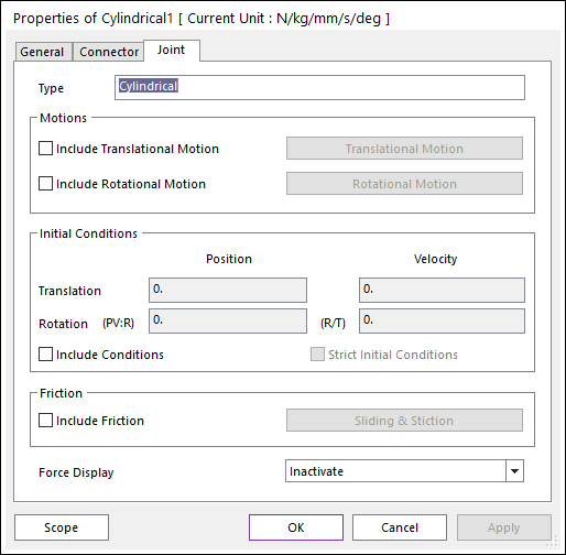
Figure 6.160 Cylindrical property page [Joint page]
Type: Shows the type of joint.
Motions: Defines the motion of the cylindrical joint. Refer to Motion.
Include Translational Motion: If this option is checked, the user can define the translational motion.
Include Rotational Motion: If this option is checked, the user can define the rotational motion.
Initial Conditions
Include Conditions: If checked, enables the user-specified initial conditions (position and velocity). Note that if Include Conditions is checked, then both Translation and Rotation initial conditions are used.
Translation: The definition is identical to the Translational Joint. See Translational Joint for more details.
Position: The initial signed distance from the joint’s base marker to the action marker, specified in Length units.
Velocity: The initial relative translational velocity between the two bodies, specified in units Length/Time.
Rotation: The definition is identical to the Revolute Joint. See Revolute Joint for more details.
Position: The initial joint angle, specified in Degrees.
Velocity: The initial velocity of the revolute joint, specified in Radians/Time.
Strict Initial Conditions: Indicates that the initial condition settings should be strictly enforced. See Common UI Joint for more details.
If a cylindrical joint is connected to an FFlex body that is include in Position and Velocity Pre-Analysis and initial conditions are specified for the Cylindrical Joint, the initial rotation must be greater than -90 degrees and less than 90 degrees.
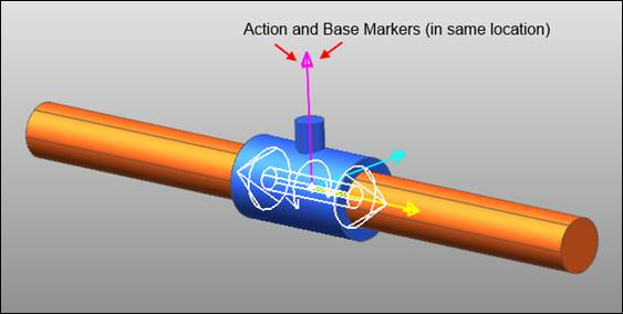
Figure 6.161 A cylindrical joint with Initial Conditions of 0 for Translation and 0 Degree for Rotation
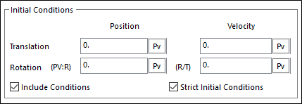
Figure 6.162 The Initial Conditions specified in the Joint tab of the Cylindrical Joint Property dialog box to achieve Fig. 2a
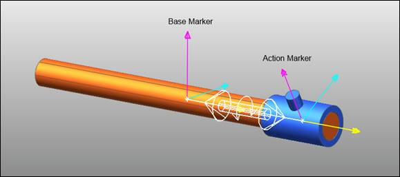
Figure 6.163 A cylindrical joint with Initial Conditions of 200 for Translation and 30 Degrees for Rotation
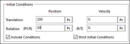
Figure 6.164 The Initial Conditions specified in the Joint tab of the Cylindrical Joint Property dialog box to achieve Fig. 3a
Include Friction: If this option is checked, the friction force can be defined for the cylindrical joint.
Force Display: Displays the resultant force vector graphically on Working Window.
6.2.2.3.2.1. Joint Friction
A friction force that contains a sliding and stiction algorithm can be defined on the cylindrical joint. Include Friction option in Joint property page must be checked to use the friction force.
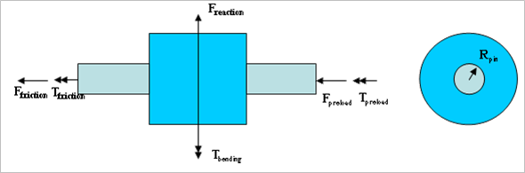
Figure 6.165 Configuration of Sliding and Stiction Friction Force on Cylindrical Joint
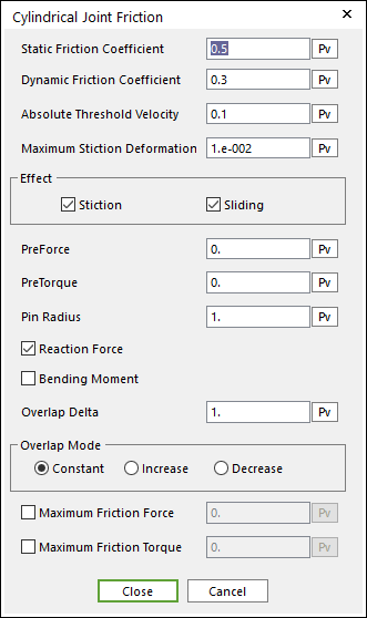
Figure 6.166 Cylindrical Joint Friction dialog box
The frictional force and torque are calculated according to the following equations:
\(\begin{aligned} & {{F}_{friction}}=\mu ({{F}_{reaction}}+(1/{{X}_{s}}){{T}_{bending}}+(1/{{\mu }_{s}}){{F}_{preload}}) \\ & {{T}_{friction}}=\mu ({{R}_{pin}}{{F}_{reaction}}+({{R}_{pin}}/{{X}_{s}}){{T}_{bending}}+({{R}_{pin}}/{{\mu }_{s}}){{F}_{preload}}+(1/{{\mu }_{s}}){{T}_{preload}}) \\ \end{aligned}\)
- where,
- \({{X}_{s}}={{X}_{s0}}\) (Constant)\({{X}_{s}}={{X}_{s0}}+{{d}_{ij}}\) (Increase)\({{X}_{s}}={{X}_{s0}}-{{d}_{ij}}\) (Decrease)\({{d}_{ij}}\) : Distance between \(i\) marker and \(j\) marker
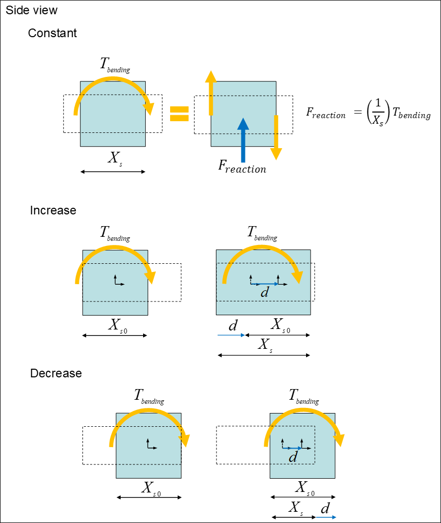
Figure 6.167 Detail of Overlap Mode and Delta
Where, the inputs into the equation are defined in the following table:
Current Friction Coefficient |
\(\mu\) |
The coefficient of friction calculated during the simulation is a function of the relative velocity between body surfaces. |
Static Friction Coefficient |
\({{\mu }_{s}}\) |
The coefficient of friction is zero at a zero velocity, but it smoothly transitions to the static coefficient of friction at Absolute Threshold Velocity (\(\Delta v\)). |
Effect |
Checks Stiction or Sliding.
\({{\mu }^{sliding\text{ }only}}=-{{\mu }_{v}},\text{ }{{\mu }_{v}}^{\max }={{\mu }_{d}}\)
\({{\mu }^{stiction\text{ }only}}=-\left( 1-\beta \right){{\mu }_{\delta }}-{{\mu }_{v}},\text{ }{{\mu }_{v}}^{\max }={{\mu }_{s}}\)
For more information, click here.
|
|
Pre Force |
\({{F}_{preload}}\) |
A constant frictional force that acts during the entire simulation. |
Pre Torque |
\({{T}_{preload}}\) |
A constant frictional torque that acts during the entire simulation. |
Pin Radius |
\({{R}_{pin}}\) |
The radius of the smaller surface geometry in the revolute joint. |
Reaction Force |
\({{F}_{reaction}}\) |
The force in the joint calculated during the simulation in the direction along the rotational axis. |
Bending Moment |
\({{T}_{bending}}\) |
The calculated torque that acts at right angles to the rotational axis. |
Overlap Delta |
\({{X}_{s0}}\) |
A distance that starts at a nominal value and increases according to the translation of the action body with respect to the base body. |
Overlap Mode |
Selects Constant, Increase, or Decrease. |
|
Maximum Friction Force |
\({{F}_{\max }}\) |
Collisions during contact as well as transitions during sliding forces can result in force spikes. High frictional forces can result from these spikes. This option allows a maximum friction force to be defined that should correspond to the maximum expected steady-state force. |
Maximum Friction Torque |
\({{T}_{\max }}\) |
Collisions during contact as well as transitions during sliding forces can result in force spikes. High frictional torques can result from these spikes. This option allows a maximum friction torque to be defined that should correspond to the maximum expected steady-state force. |