6.4.2.3. Geo Cylinder
A Geo Cylinder Contact generates a force between a geometry and the other cylinder. The geometry can be a rigid body or a flexible body and they can have any kind of shapes. This is a derived concept for Geo Surface contact and it is possible to switch to Geo Surface contact. In the case of action cylinder geometry, it can be analyzed more quickly and accurately than Geo Surface contact.
Note
In Geo Cylinder Contact, only rolling face in Cylinder geometry is considered when calculating contact force.
6.4.2.3.1. Modeling Options
In the case of Geo Cylinder contact, a cylinder geometry type is supported for an action geometry. Solid, shell, and surface geometry types are supported about rigid body and patch set is supported about flexible body for a base geometry when creating.
Solid(Shell, PatchSet), Cylinder
Solid(Shell, PatchSet): Selects a solid or a shell or a patch set to define a base solid.
Cylinder: Selects a cylinder to define an action cylinder.
Solid(Shell, PatchSet), MultiCylinder
Solid(Shell, PatchSet): Selects a solid or a shell or a patch set to define a base solid.
MultiCylinder: Selects some cylinders to define action cylinders.
Solid(Shell, PatchSet), Cylinder, Solid(Shell, PatchSet), Cylinder
Solid(Shell, PatchSet): Selects a solid or a shell or a patch set to define a base solid.
Cylinder: Selects a cylinder to define an action cylinder.
Solid(Shell, PatchSet): Selects a solid or a shell or a patch set to define another base solid.
Cylinder: Selects a cylinder to define another action cylinder.
MultiSolid(Shell, PatchSet), MultiCylinder
MultiSolid(Shell, PatchSet): Selects some solids or shells or patch sets to define base solids.
MultiCylinder: Selects some cylinders to define action cylinders.
Surface(PatchSet), Cylinder
Surface(PatchSet): Selects a surface or a patch set to define a base solid or FFlex body.
Cylinder: Selects a cylinder to define an action cylinder.
Surface(PatchSet), MultiCylinder
Surface(PatchSet): Selects a surface or a patch set to define a base solid or FFlex body.
MultiCylinder: Selects some cylinders to define action cylinders.
Surface(PatchSet), MultiCylinder, Surface(PatchSet), MultiCylinder
Surface(PatchSet): Selects a surface or patch set to define a base solid or FFlex body.
MultiCylinder: Selects some cylinders to define action cylinders.
Surface(PatchSet): Selects a surface or patch set to define another base solid or FFlex body.
MultiCylinder: Selects some cylinders to define action cylinders.
MultiSurface(PatchSet), MultiCylinder
MultiSurface(PatchSet): Selects some surfaces or patch sets to define base solids or FFlex bodies.
MultiCylinder: Selects some cylinders to define action cylinders.
6.4.2.3.2. Properties
In the case of Geo Cylinder contact, the property page is same to Geo Surface contact. For more information, click here.
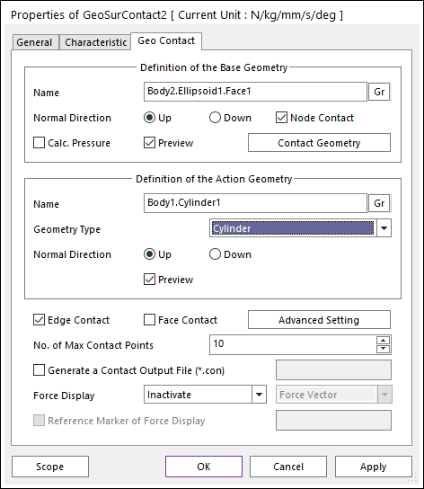
Figure 6.332 Properties of Geo Cylinder Contact dialog box
Node Contact: If this option is checked, contact force is calculated when base nodes are penetrated into the cylinder.
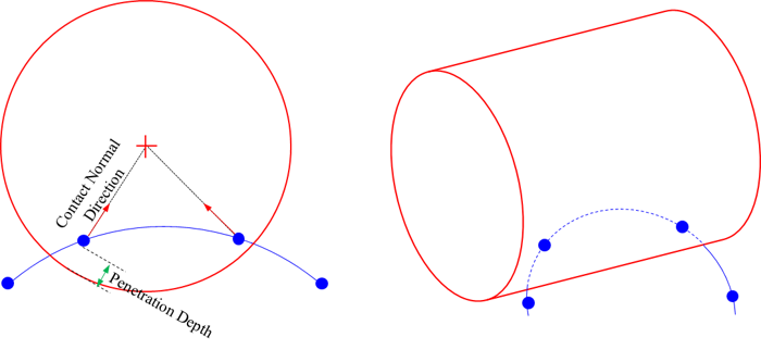
Figure 6.333 Definition of Node Contact Pattern [Cylinder Type]
Edge Contact: If this option is checked, contact force between cylinder and edge is calculated. Detail geometrical definition follows below figure.
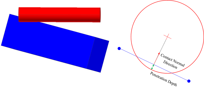
Figure 6.334 Definition of Edge Contact Pattern [Cylinder Type]
Face Contact: If this option is checked, contact force between cylinder and face is calculated. Detail geometrical definition follows below figure.
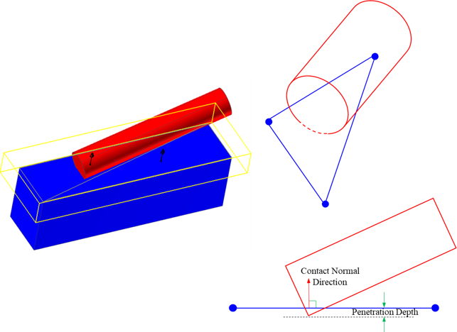
Figure 6.335 Definition of Face Contact Pattern [Cylinder Type]