6.3.2.1. Spring
A spring can represent a physical spring and/or a physical damper (such as a shock absorber) that acts between two points on two different bodies.
A spring force can be defined with spring data (spring and damping coefficients, etc.) or with spline data. Spring values may be provided by the spring vendor or they can be determined by the physical tests. The stiffness coefficient can be directly measured (force/displacement). Damping can be determined by hanging a mass from the spring, stretching the spring, and counting the cycles until the system comes to rest. Then, the damping coefficient can be adjusted in a RecurDyn model until the dynamic behaviors match.
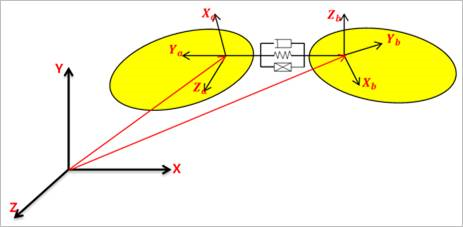
Figure 6.245 TSDA system
6.3.2.1.1. Modeling Options
The user can create a force entity as follows.
Point, Point
Point: Selects a point on a base body. This point defines a location on which the reaction force is applied.
Point: Selects a point on an action body. This point defines a location on which the action force is applied.
Body, Body, Point, Point
Body: Selects a base body of spring force.
Body: Selects an action body of spring force.
Point: Selects a point on a base body. This point defines a location on which the reaction force is applied.
Point: Selects a point on an action body. This point defines a location on which the action force is applied.
6.3.2.1.2. Properties
Spring Page
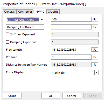
Figure 6.246 Spring property page [Spring page]
The magnitude of the spring force is calculated according to the following equations:
\({{F}_{S}}=-K{{(l-{{l}_{f}})}^{m}}-C{{\dot{l}}^{n}}+F,\text{ }{{F}_{b}}=-{{F}_{a}}\)
Where, the inputs into the equation are defined in the following table:
Stiffness Coefficient |
\({{K}}\) |
Enter the coefficient that determines spring stiffness, namely the change in the spring force given a change in length (units are force/length). |
Stiffness Spline |
Fill in values of spring lengths and spring forces that cover the range of extension and retraction of the spring. For more information, click here. |
|
Damping Coefficient |
\({{C}}\) |
Enter the coefficient that determines the damping force given the relative velocity of the spring endpoints (units are force-time/length). |
Damping Spline |
Fill in values of spring velocities and damping forces that cover the range of positive and negative velocities in the spring. For more information, click here. |
|
Stiffness Exponent |
\({{m}}\) |
Specify an exponent that is applied to the change in spring length from the free length. |
Damping Exponent |
\({{n}}\) |
Specify an exponent that is applied to the rate of change of the spring length (spring velocity). |
Free Length |
\({{{l}_{f}}}\) |
Enter the length of the spring where it exerts no force other than the Pre-load. The default free length is the length of the spring when it is first defined. |
Current Length |
\({{{l}}}\) |
The current length of spring. |
Pre Load |
\({{{F}}}\) |
Specify an extra load or force in the spring. The force in the spring at its free length is the Preload. |
Distance between Two Markers: Displays the distance between the base marker and the action marker. When clicking R, the distance between the action marker and the base marker is recalculated.
Force Display: Displays the resultant force vector graphically on Working Window.
Graphic Page
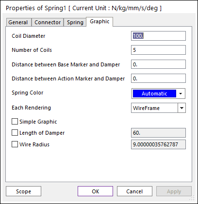
Figure 6.247 Spring property page [Graphic page]
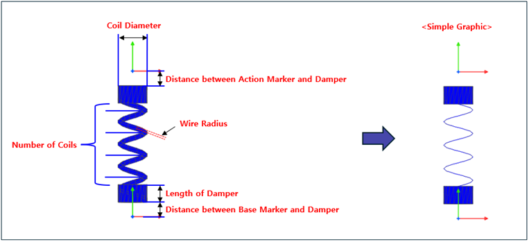
Figure 6.248 Definition of graphic options for the spring
Coil Diameter: Defines the diameter of the spring graphic.
Number of Coils: Defines the number of coils of spring graphic.
Distance between Base Marker and Damper: Defines the distance between a base marker and damper.
Distance between Action Marker and Damper: Defines the distance between an action marker and damper.
Spring Color: Defines the color of the spring graphic.
Each Rendering: Defines the rendering option in Each Rendering mode.
WireFrame: Displays a body as wire frame in Each Rendering mode.
Shade: Displays a body as shade in Each Rendering mode.
ShadeWithWire: Displays a body as shade with wire in Each Rendering mode.
Hide: Does not display a body on Working Window in Each Rendering mode.
Simple Graphic: If this option is checked, the spring graphic is changed as simple shape.
Length of Damper: Defines the length of damper.
Wire Radius: Defines the radius of the wire of the spring.
Note
If a stiffness coefficient and a damping coefficient are entered the expressions by Parametric Value, these parameters are always applied each initial value of the expression. So, the entered values are not changed. To change the entered values by expressions, use the axial force, the translational force, the screw force, etc.
Definition of Spring Force using Splines
As explained in the section on sign convention for spring curves, the extension of the spring generates a negative force and compression of the spring generates a positive force. However, for the convenience of the user the spring stiffness splines should be defined with a positive slope, as shown below:
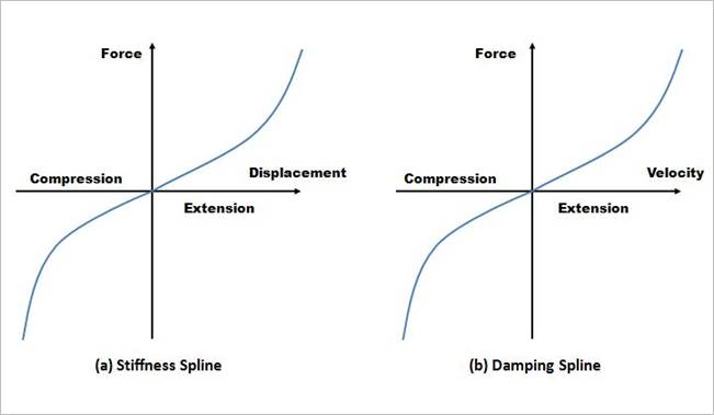
Figure 6.249 Spline for a force curve
Relation to Free Length and Pre Load
If the preload and the decrement item are not considered, the force by the spring appears as below Figure 6.250. In this case, the force is 0 when the value of distance between two markers is same with the value of free length.
When the value of distance between two markers is smaller than the value of free length, it generates the plus force considered the compressed state.
When the value of distance between two markers is bigger than the value of free length, it generates the minus force considered the tensile state.
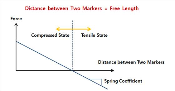
Figure 6.250 Force by the Spring
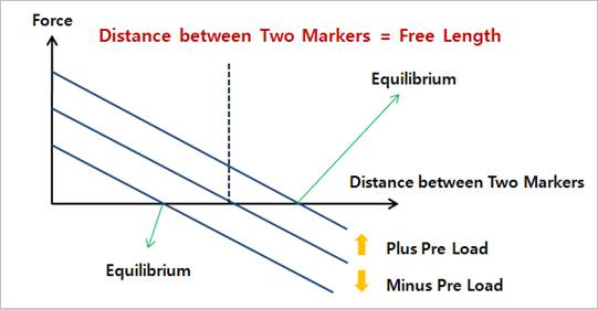
Figure 6.251 Force as the Equilibrium State
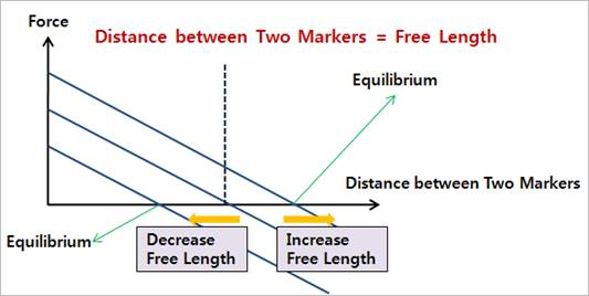
Figure 6.252 Decrease and Increase Free Length
Spring Force Sign Convention
It can be confused to understand the sign convention of the spring forces. A simple model is selected to explain the sign convention. Figure 6.253 shows a simple model that consists of an orange block that slides horizontally. As the block slides, the spring is first stretched and then compressed as a translational joint with a motion input moves the block. The force exerted by the translational joint motion driver is given by the blue curve. The force in the spring is shown as the green curve. Note that there is no pre-load in the spring.
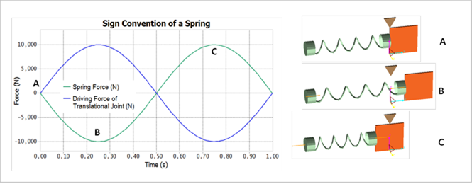
Figure 6.253 Sign Convention for a Spring Express with a Simple Model
Therefore when the spring is stretched or extended from its free length it exerts a negative force between the connected bodies. Likewise when the spring is compressed it exerts a positive force.
Another way of looking at the sign convention is that when the starting force of a spring is positive it pushs apart the two connected bodies. Likewise if the starting force of a spring is negative it pulls together the two connected bodies.
The sign convention of the damping force in the spring is that the damping force always opposes the separation velocity between the two end points of the spring. If the spring is increasing in length then the damping force pushes to try to decrease the spring length. Likewise if the spring is decreasing in length then the damping force pushes to try to increase the spring length.