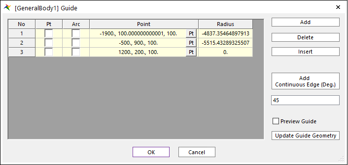
Insert: Creates a row above the row selected in Guide list.
Add Continuous Edge (Deg.): When an edge is selected, all of the connected edges within the user-defined tolerance angle are selected at the same time.
Preview Guide: Preview the set guide status.
Update Guide Geometry: Updates the state of the guide that has changed.
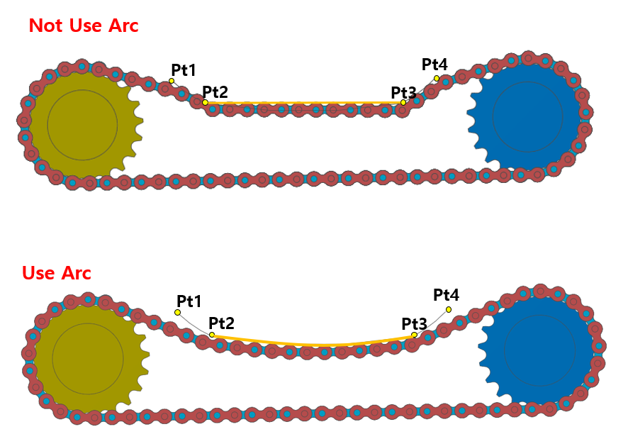
Pt: Create assembly using the point when creating an assembly.
Figure 42.8 Assembly shape depending on whether points are used or not
Arc: Create assembly using the radius value.
Figure 42.9 Assembly shape depending on whether Arc is used or not
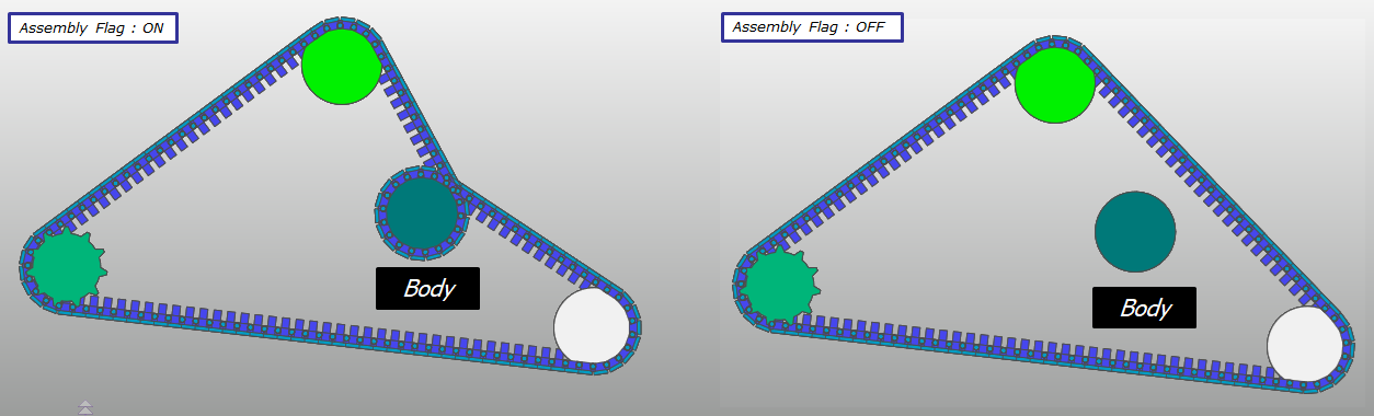
Assembly: Check to include passing Body, Point, or Guide when performing assembly.
Note
As assembly proceeds, the shape of the assembly is determined by the x-y plane of the geometry reference frame of the first passing body.
Therefore, please align the geometry reference frame of the first body with the same shape as the assembly and proceed.
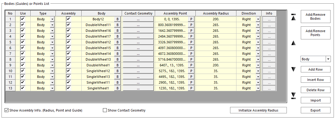
Body: Define passing body such as rigid body or flexible body except toolkit body.
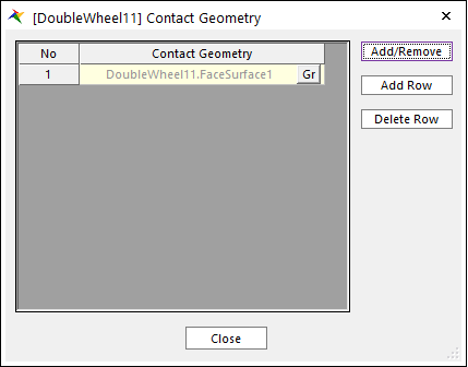
Contact Geometry: Defines the contact geometry of the passing body that is in contact with the assembly body.
Note
If a surface or curve is defined in the passing body, it is automatically added to the contact geometry when the assembly page is opened.
So, if the contact geometry is defined as a surface or curve in advance, the assembly process can be greatly reduced.
Figure 42.11 Definition of Contact Geometry dialog box
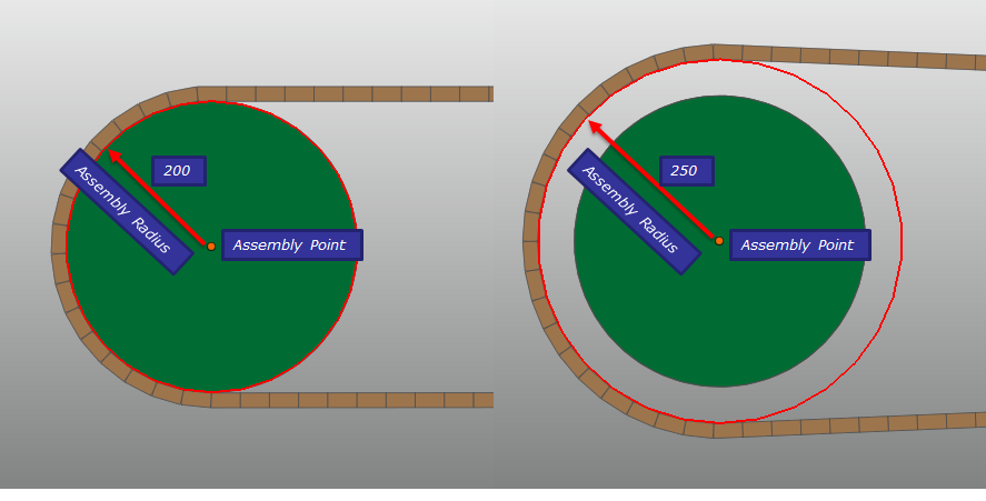
Assembly Point, Assembly Radius: The point and radius used when assembling the passing body of Body type.
Figure 42.12 Definition of Assembly Point and Radius
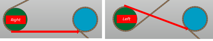
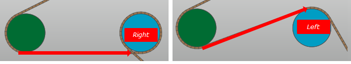
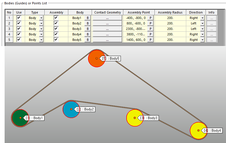
Direction: Defines the winding direction on the passing body when performing assembly. Right means winding in a counterclockwise direction based on the normal direction of the passing body, and Left means winding in a clockwise direction.
Figure 42.13 Definition of Assembly Direction of first passing body
Figure 42.14 Definition of Assembly Direction of second passing body
Add/Remove Bodies: Select the entire body to use as the passing body.
Add/Remove Points: Select the entire points to use as the passing point.
Note
Please note that if you use Add/Remove Bodies and Add/Remove Points functions, the existing Bodies (Guides) or Points List information will be deleted.
Add Row: Add one last row to the Bodies (Guides) or Points List.
Insert Row: Create a row above the row selected in Bodies (Guides) or Points List.
Delete Row: Delete the row selected in Bodies (Guides) or Points List.
Import: Import the xml file containing Bodies (Guides) or Points List information.
Export: Export to xml file containing Bodies (Guides) or Points List information.
Note
Since the information of Bodies (Guides) or Points List is lost once assembly is performed, it is recommended to save the List by using the export function before making assembly.
Show Assembly Info. (Radius, Point and Guide): Show assembly information.
Show Contact Geometry: Show each selected contact geometry on the passing entity.
Initialize Assembly Radius: Set the assembly radius of the passing body to the initial value.