32.1.1. Step to define Global Data
Click the Data icon of the Crank group in the Crank tab. The user can see Pre Crank Global Data Dialog.
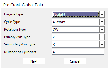
Figure 32.2 Pre Crank Global Data dialog box
Engine Type: There are three kinds of Engine type. They are Straight, V type and Horizontal type.
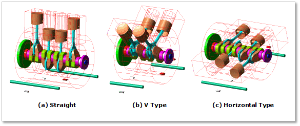
Figure 32.3 Types of engine
Cycle Type: Select an engine cycle 2 or 4 stroke. In the 2 stroke engine system, a process of ‘Suction – Compression – Explosion – Exhaust’ occurs during 1 rotation of Crank Shaft. However, in the 4 stroke engine system, the process occurs during 2 rotation of Crank Shaft. So, the Cycle Type is related with Firing Angle and Gas pressure profile.
Rotation Type: Select the crankshaft’s direction of rotation, which is CW (clock-wise) or CCW (counter-clock-wise). And then the crankshaft’s direction of rotation is decided.
Primary Axis Type: Select the axis which direction can be the rotating axis of crank shaft.
Secondary Axis Type: Select the axis which direction can be the cylinder’s direction.
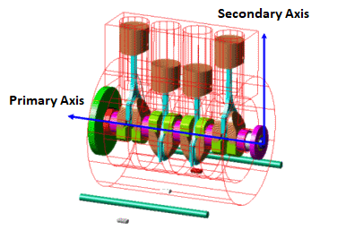
Figure 32.4 Primary & Secondary Axis of Crank System
Number of Cylinder: Enter the value of number of cylinders that can be created.
Previous defined values are the basic information to create the crank system. After this data is confirmed, each value is unchangeable. So, if Next is clicked, warning message is displayed.
After that, the Crank Global Data Dialog is opened.
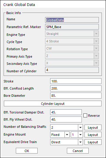
Figure 32.5 Crank Global Data dialog box
Name: Means that the values the user entered are defined in Global Data
Parametric Ref. Marker: Checks the parametric marker for crank system. SPM_Base controls the whole system. It cannot be modified.
Stroke: Is a distance between TDC (Top Dead Center) and BDC (Bottom Dead Center). If the user changes the value of stroke, rotation diameter of crank shaft pin is changed to be same with the value of stroke.
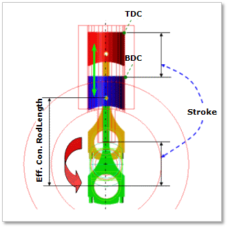
Figure 32.6 Stroke of engine
Eff.Con. Rod Length : Defines the distance between the center point of crankshaft’s pin body and piston pin.
Bore diameter: Defines a diameter of cylinders. If the user changes this value, a piston head diameter is also changed. Because the values are defined by SPV_Cylinder_Diameter_i which is Special Parametric Value.
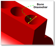
Figure 32.7 Bore Diameter
Eff. Torsional Damper Dist.: Defines a distance from the center point of the first main body of crank shaft to the center of a Torsional Damper.
Eff. Fly Wheel Dist.: Defines a distance from the center point of the last main body of crank shaft to the center of a Fly Wheel.
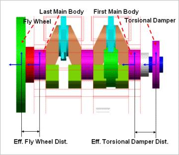
Figure 32.8 Eff. Torsional Damper Distance&Eff. Fly Wheel Dist
Number of Balancing shafts: Selects the number of balancing shafts in Figure 32.5.
If the user clicks Layout of balancing shaft in Figure 32.5, Balancing Shaft Layout Dialog is opened. In this dialog box, the user can confirm and define the position of SPM of each Balancing Shaft. There are two kinds of Input method. One is the X-Y-Z Input Method. The other is the R-Theta-Z Input Method.
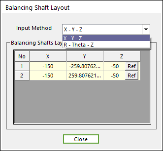
Figure 32.9 Balancing Shaft Layout dialog box
If the user clicks Ref in Figure 32.9, the user can confirm the information of SPM which is reference marker of Balancing Shaft, such as the name of SPM, the origin of SPM and the orientation of SPM.
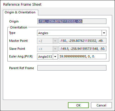
Figure 32.10 Reference Frame dialog box
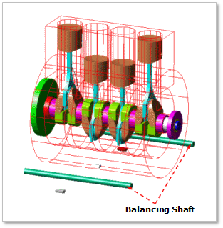
Figure 32.11 Number of Balancing Shaft
Engine Mount: The user can mount the engine block to the ground using Fixed Joint or Bushing Force.
If the user clicks Layout of Engine Mount in Figure 32.5, Engine Mount Layout dialog box is opened. In this dialog box, the user can define the position of SPM of Engine Mount. There are two kinds of Input method. One is the X-Y-Z input method. The other is the R-Theta-Z Input method.
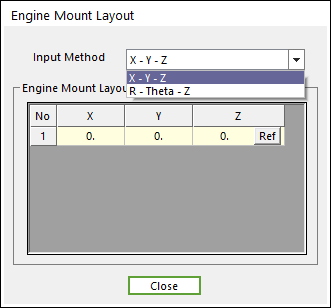
Figure 32.12 Engine Mount Layout dialog box
If the user clicks Ref, the user can confirm the information of SPM which is reference marker of Engine Mount, such as the name of SPM, the origin of SPM and the orientation of SPM.
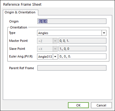
Figure 32.13 Reference Frame Sheet dialog box
Equivalent Drive Train (EDT): In whole engine system, when a crank shaft is rotated, resisting force is generated against Crank Shaft caused by EDT (Equivalent Drive Train) which is connected with Crank Shaft. The EDT can include transmission, clutch, drive shaft, chain, wheel, tire and so on. It is represented as equivalent moment of inertia and stiffness including speed ratio. In general, three types of EDT are used in automotive system. These are direct-drive, gear-drive and belt-drive.
If the user clicks Layout of Equivalent Drive System in Figure 32.5, EDT Layout Dialog is opened. In this dialog box, the user can define the position of SPM of EDT. There are two kinds of Input method. One is X-Y-Z input method. The other one is R-Theta-Z Input method.
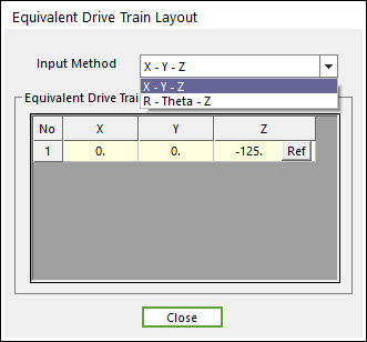
Figure 32.14 Equivalent Drive Train Layout dialog box
If the user clicks Ref, the user can confirm the information of SPM which is reference marker of EDT, such as the name of SPM, the origin of SPM and the orientation of SPM.
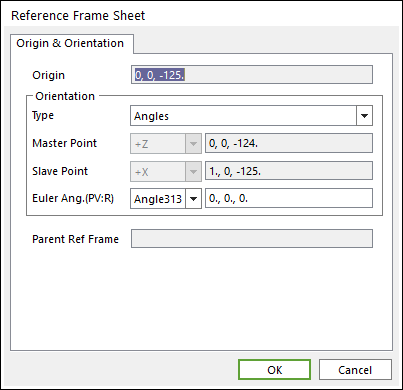
Figure 32.15 Reference Frame Sheet dialog box
After setting all parameters, click OK.
The user can define the geometric and connection information using the Component Builder.