28.2.4. Center Flange
A Center flange is a body consisting of three cylinders. The width and radius of the contact surface of Center flange must be large enough for the track link to pass by it. The Center flange is used as a roller for hydraulic excavators and small size bulldozers.
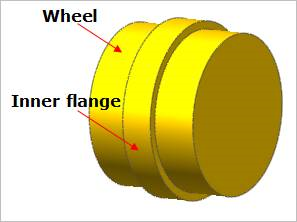
Figure 28.25 Center flange geometric entity
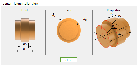
Figure 28.26 Center flange dimension information
Wf |
Inner Flange width |
Wt |
Total Width |
Rf |
Inner Flange Radius |
Rw |
Wheel Radius |
28.2.4.1. Modeling Options
The user can create a center flange as follows.
Point, Distance
Point: Selects a point to define the center of the center flange.
Distance: Defines a distance of the center flange.
28.2.4.2. Properties
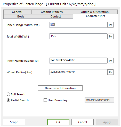
Figure 28.27 Center Flange property page [Characteristics page]
The Center Flange property page is shown in Figure 28.27. The parameters are explained below. In order to understand the geometry, refer to Dimension Information.
Inner Flange Width (Wf): Enters the width of inner flange.
Total Width (Wt): Enters the total width for inner flange and wheel.
Inner Flange Radius (Rf): Enters the radius of inner flange.
Wheel Radius (Rw): Enters the radius of wheel.
Full Search: All links are searched for contact.
Partial Search: Some links are searched for contact in some boundary. It is used to reduce total solving time.
User Boundary: The radius of neighbor range.
Contact between a Center Flange and Track Links
The center flange is in contacts with the track link in the two parts.
The top surface of track link - the wheel surface of center flange
The inner surface of track link - the inner flange of center flange
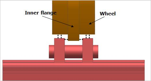
Figure 28.28 Contact between a Center flange and the track links