31.2.1. Step to Create Flexible Web Gear
There are two ways to create a Flexible Web Gear: using the Web and importing Gear CAD. It is recommended to check whether Geometry Data of gear is properly applied at each step of creating Web, FDR, and FlexWeb. After the Flexible Web Gear is created, it is created as a Group, so if you want to create an FDR in the gear hole, you must use the Del.Teeth function. Teeth created in Flexible Web Gear is a Clone body, so only Involute Contact can be used. Flexible Web Gear is available for both FFlex and RFlex, but considering the analysis time, RFlex is recommended.
Step to create RFlex Web Gear
Click the Web ribbon button in Flexible Gear group and input the Geometry Data, Tooth Profile and Web of the gear to create Web.
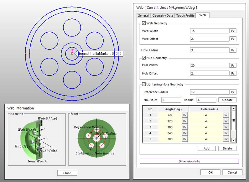
Figure 31.75 Web dialog box
Mesh the created Web with desired parameters and exit the Mesh mode.
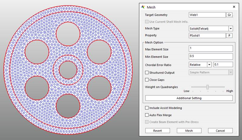
Figure 31.76 Meshing the Web Geometry
Note
To connect the shaft and the joint to the center of the gear hole, you need to create an FDR. Below is how to create an FDR.
Create a node with the Node ribbon button of the FFlex Edit group at the location where the joint is connected.
Click the Node Set ribbon button of the Set group and create a node set at the gear hole with Add / Remove (Continuous) of the Node Set tab.
Click the FDR ribbon button of the FFlex Edit group, select the node created in Step 1 for the Primary Node, and select the node set created in Step 2 for the Node Set.
Click FDR ribbon button in Flexible Gear group and select the Web flexible body. Check the Geometry Data and Tooth Profile and click OK to create FDR.
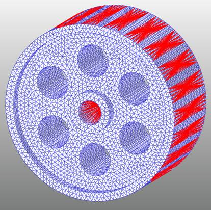
Figure 31.77 FDR of Web Flexible body
- In Flexible tab in ribbon menu, click G-Manager and select Web FFlex body. Convert the FFlex body to RFlex body.For more information about G-Manager, refer to (7) RFlex : Swap using RFlexGen.
In Gear tab in ribbon menu, Click FlexWeb and select Web RFlex body. Check the Geometry Data and Tooth Profile and click OK to create Flexible Gear.
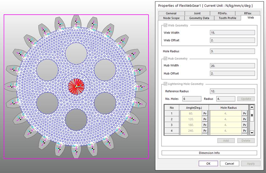
Figure 31.78 Web Flexible Gear
Step to create Flexible Web Gear using imported CAD
Click Gear in Toolkit ribbon menu and import Gear CAD in Gear subsystem.
Rotate the Gear CAD so that the center axis is parallel to the +Z axis.
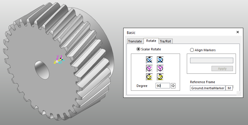
Figure 31.79 Rotating Gear CAD to +Z Axis
- Create Gear at the center of Gear CAD according to Gear CAD specifications. If the teeth of the created Gear and Gear CAD do not match, rotate Gear CAD to fit exactly.To calculate the exact rotation angle of the gear, create a marker in the teeth center of each gear and use the Angle Measure in Home tab.
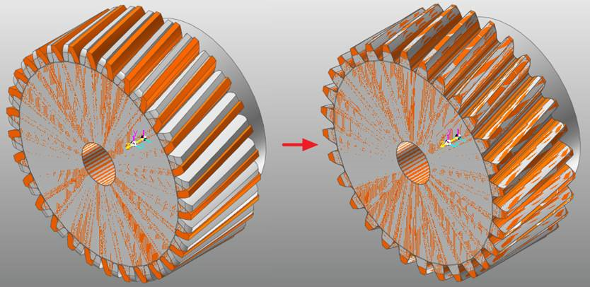
Figure 31.80 Rotating Gear CAD to +Z Axis
- Enter the Body Edit mode of Gear CAD and create Circle at the face of Gear CAD with radius of root diameter.Extrude the Circle in -Z direction using Extrude Surface. Use Split Solid to separate Teeth and Web of Gear CAD.Delete all entities except Web of Gear CAD.
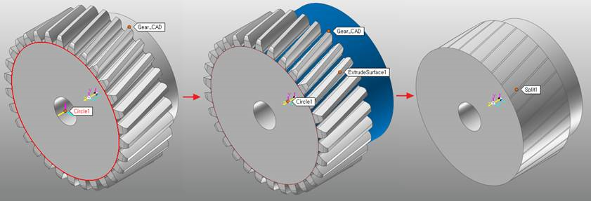
Figure 31.81 Using CAD function to get Web Geometry
Follow the step 2~5 from Step to create RFlex Web Gear. Remember to check the Geometry Data and Tooth Profile in each step.