It allows the user to enter Ground Mode in order to define a road terrain. The road data is used for the vehicle analysis such as Automotive Analysis and Low Mobility Tracked Vehicle Analysis.
Because only one road terrain can be defined, the earlier generated terrain is removed if the user tries to make multiple road terrains. For reference, when there are several levels of subsystems, the just road data defined in the current subsystem is available when performing a simulation.
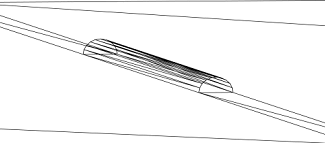
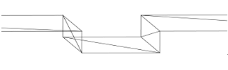
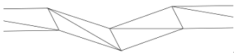
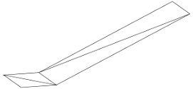
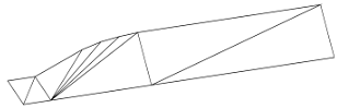
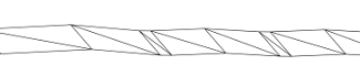
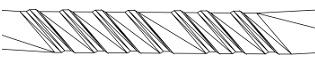
It allows the user to create a road by using more than two user-defined outline curves. At that time, the number of point data of outline curves should be same. The operation is the same to Outline Surface.
Spline Road
It allows the user to create a road by using more than two user-defined spline curves. At that time, the number of point data of spline curves should be same. The operation is the same to Spline Surface.
Face Road
It allows the user to create a road directly from the created geometry such as a surface and a solid geometry. For reference, the extracted face surfaces can be used for the road. he operation is the same to Face Surface.
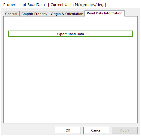
6.1.3.10.2. Create a Road Data using Make Road Data
Create Outline Surface. To see how to do modeling this, click here. Besides Outline Surface, the user can create road data from Spline Surface and Face Surface.
The user can import a pre-defined ground profile from the library which is located in the directory (<Install Dir>\Help\Examples\Track_RDF) or the user-defined ground profile.
The various pre-defined terrain profiles for the high mobility tracked vehicle, include bumping courses, trench course, inclined courses, and standard cross-country courses.
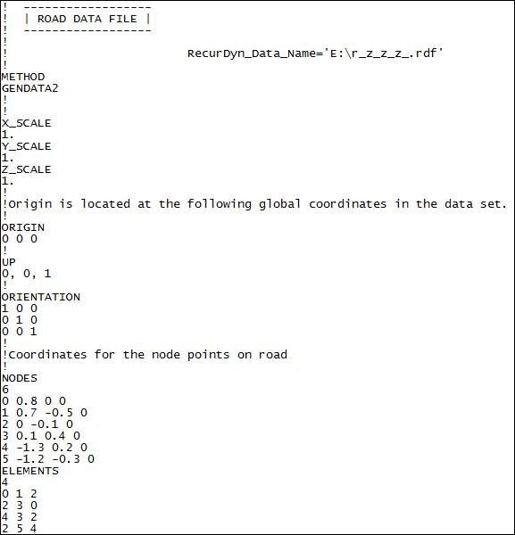
The information about the road in the general road profile format.
X_SCALE
real
Conversion Factor.
Y_SCALE
real
Conversion Factor.
Z_SCALE
real
Conversion Factor.
ORIGIN
Coordinates the road origin with respect to the global reference frame.
x, y, z
UP
A vector that indicates the upward side of the road in the global reference frame.
x, y, z
ORIENTATION
Transformation matrix which is oriented to the road coordinate system with respect to the global reference frame.
x1, y1, z1
x2, y2, z2
x3, y3, z3
NODES
Number of nodes (N)
Integer number of nodes.
Node_1, x_1, y_1, z_1
Location of Node 1.
Node_2, x_2, y_2, z_2
Location of Node 2.
Node_n, x_n, y_n, z_n
Location of Node n.
ELEMENTS
Number of elements (Ne)
Integer number of elements.
NodeA_1, NodeB_1, NodeC_1,U0_1, U1_1
Nodes which are consisted of triangle element 1.
NodeA_2, NodeB_2, NodeC_2,U0_2, U1_2
Nodes which are consisted of element 2.
NodeA_n, NodeB_n, NodeC_n,U0_n, U1_n
Nodes which are consisted of element n.
Example
User-Defined Road Data File Format
This road data file is defined by only the user. So, RecurDyn does not generate this Road File. And it can be imported by Import Road on the Road Data group.
The following table explains the format of the user-defined Road Data file.
Definition of the start position for the road data
NORMAL_DIRECTION
Definition of the normal direction for the road data.
DRIVING_DIRECTION
Definition of the driving direction for the road data.
OFFSET
Vertical offset to the ground with respect to the inertial frame.
WIDTH
Definition of the width between two outlines.
(DATA)
Definition of the road data points.
direction
Definition of the position along the driving direction.
left
Definition of the position to the left side with respect to the driving direction.
right
Definition of the position to the right side with respect to the driving direction.
Example
!
! road data file for RecurDyn road data !
$--------------------------------------------------------------------------UNITS
[UNITS]
LENGTH            = 'mm'
$---------------------------------------------------------------------PARAMETERS
[PARAMETERS]
START_POSITION       =  0,0,0  $ definition of the road start point
NORMAL_DIRECTION    =  Y      $ definition of the normal direction of road data.
DRIVING_DIRECTION    =  X      $ definition of the driving direction of road data.
OFFSET                  =  -100      $ vertical offset to the ground with respect to the inertial frame
WIDTH                   =  500    $ definition of the width between two outlines.
$
$ direction   left       right
(DATA)
    0             0          0
  100           100        100
  200           100        100
  300           -50        -50
  500            50         50
  600            10         10
  700             0          0
  800             0          0
  900             0          0
  1000           30         30
  1500            0          0