2.2.15. Status Bar
This panel provides a variety of information. The quick help is provided on the left. The coordinate system type is indicated. If you are in the simulation process, the progress information is added.
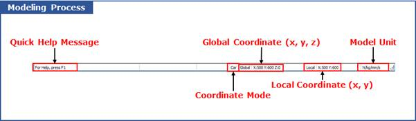
Figure 2.142 Status Bar in the Modeling Process
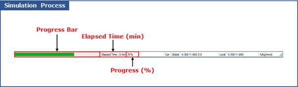
Figure 2.143 Status Bar in the Simulation Process
Quick Help Message
This message helps you to create an entity. For example, if the cursor is located on the cylinder icon in the toolkit bar, the user can see the below message in status bar.

This message means that the first point is required as an input. You can click a point in the working plane or input the coordinate of the point in the command line. After inputting the first point, you see the next message.

This message means that the second point is defined by clicking a point in the working plane or inputting the coordinate of the point in the command line.
Coordinate Mode
You can indicate a coordinate type
CA: Cartesian Coordinate
CY: Cylindrical Coordinate
The cursor position with respect to the reference frame of working plane is automatically changed to the r-theta convention when the cylindrical grid is selected.
Global Coordinate and Local Coordinate
The global and local positions of the cursor position with respect to the inertial reference frame and the reference frame of working plane are displayed on the middle of panel.
Model Unit
The right portion of panel contains the current model units. No user input is accepted within this toolbar.
Progress Bar and Progress
The progress of current simulation is displayed by the progress bar and %.
Elapsed Time
The elapsed time after starting a simulation is displayed.
Auto Operation
After auto operation mode is on, message is displayed.