12.3.6.1. Target Face & Type Information
The important concept is to create the mesh of regular pattern so that the number of nodes created in the face-to-face edges is same in the four faces consisted of 4 edges. In other words, if the number of nodes in the top and bottom edges is N1 and the number of nodes in the left and right edges is N2, the number of nodes is same in the face-to-face edges as below figure. So, all faces can be divided to 4-Sided and 4-Side More. Also, the specific faces without edges like the circle face and the cylinder face internally handle to create the mesh of regular pattern.
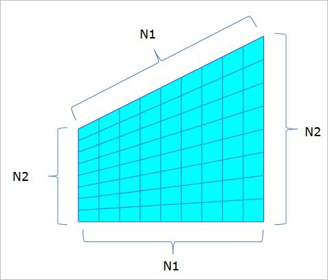
Figure 12.31 Advanced Mesh Concept about 4-Sided Face
Formal Type: Consists of 4-Sided, Circle, and Cylinder.
The results of Advance Mesh for three types. To get the same result, the user checks the Formal Type option in the dialog of Figure 12.33. The Formal Type option is basically checked to Check All so that the faces of all formal types are applied to Advanced Mesh. If the user wants to only get the information of the specific formal type, the user can see the results to select the specific formal type. If the user does not want to apply Advanced Mesh for the specific face, the user can individually check or individually clear the check boxes shown as Figure 12.33. Also, the user can check all or clear all in the top check box.
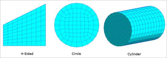
Figure 12.32 Formal Type Results
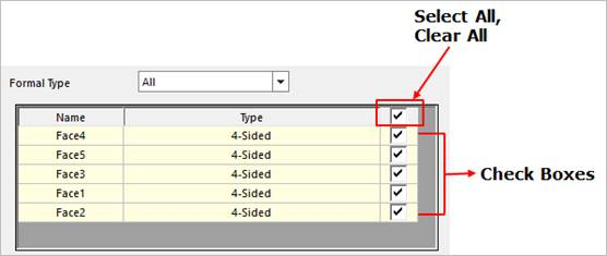
Figure 12.33 Check Boxes for selecting the formal type
Circle Type: The number of elements of the circle face edge must be set to a multiple of 8 to obtain an arranged Advanced Mesh result for the circle type.
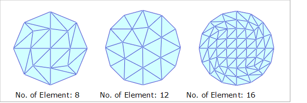
Figure 12.34 Advanced Mesh result according to the No. of elements
4-Sided More Type: In general, the information of 4-Sided More Type is included to the imported CAD geometry. This function shows all 4-Sided More faces of the geometry and helps to perform Advanced Mesh considering the 4-Sided face. If the user performs Advance Mesh for the 5-Sided face, the user should define the faces which are face-to-face shown as Figure 12.35. If the 1st edge and 2nd edge (red) are defined to a set of edges and the 4th edge (blue) is defined to the face-to-face component of the set of edges, the other edges are automatically defined to the face-to-face components in Figure 12.35. So, the 5-Sided face is performed to the mesh by converting to the 4-Sided face ((1st + 2nd), 3rd, 4th, 5th edges). Therefore, the result is like Figure 12.35.
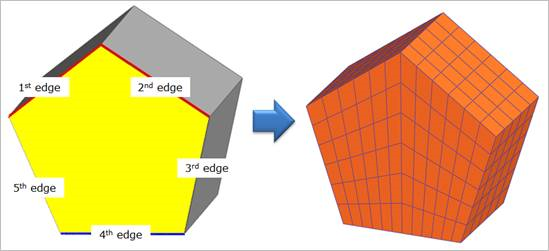
Figure 12.35 How to apply Advanced Mesh to 4-Sided More Type
The default setting is unchecked to apply Advanced Mesh for the 4-Sided More from the beginning. So, if the user cannot satisfy the mesh result after performing the mesh function to the imported CAD geometry, the user should perform the mesh function again after checking the all 4-Sided More faces. If the user selects the face name displayed in the dialog, the selected face of geometry to mesh highlighted by the yellow color and the user can individually check or individually clear the check boxes whether to apply Advanced Mesh shown as Figure 12.36. Also, the user can check all or clear all in the top check box. In Figure 12.37, the user can see the difference of mesh results for hexagonal columns whether to check the check boxes for 4-Sided More Type.
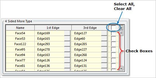
Figure 12.36 Check Boxes for selecting the 4-Sided More Type
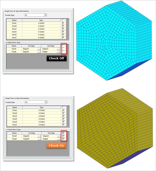
Figure 12.37 Mesh result comparison according to check on/off
To apply Advanced Mesh for the 4-Sided More face, the user should define the components of two edges which are face-to-face. The component of edge can be become an edge or a set of edges. In Advanced Mesh, the face-to face components for the 4-Sided More faces is automatically set in the 1st Edge and 3rd Edge columns shown as Figure 12.37. But the user can fail to mesh it by the combination of selecting edges although the user performs to mesh the 4-Sided More type as 4-Sided because the general face mesh is performed by the general CAD parameter. The user should selectively set the edge in the 1st Edge and 3rd Edge columns if the user defines the desired 4-Sided face for the specific face.
To select the faces which are face-to-face, the user can select a face by clicking. Then, the selected face is highlighted, and the information of face-to-face edges is distinguished the red line and the blue line. To modify the red line, the 1st edge, the user can select the 1st Edge column or the square button of the 1st Edge column to select the desired edge in the working window. To select the multiple edges as a set, the user can click them with the Shift key. Also, the user can select them again to clear the selected edges. To modify the 3rd Edge, the blue edge, the user can use the same method. For reference, if the red line connects to the blue line, the user cannot select them to modify the edges. Because it is contrary to the rule which is to define the face-to-face edges of 4-Sided face if the lines have connected each other.
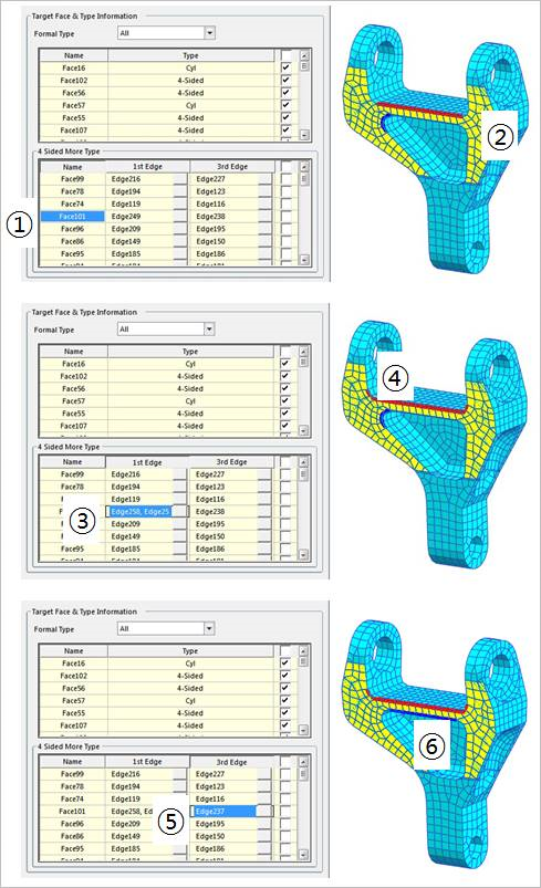
Figure 12.38 Procedure to modify edges of 4-Sided More Type