35.2.2.1. Pressure in Chamber
The pressure in this hydraulic system is determined by the following equation, based on the definition of bulk modulus.
- where,
- \(\dot{p}\) is pressure change rate\(E\) is Bulk modulus\(V\) is chamber volume\(\dot{V}\) is the sum of all changes of the volume.
\(\dot{V}={{\dot{V}}_{chamber}}+{{Q}_{valve}}+{{Q}_{leakage}}+{Q_{ReliefValve}}\)
- In this equation,
- \({{\dot{V}}_{chamber}}\) is the pressure chamber volume change rate\({{Q}_{valve}}\) is the oil flow through check valve\({{Q}_{leakage}}\) is the oil flow through the leakage gap\({{Q}_{ReliefValve}}\) is the oil flow through the Relief Valve.
35.2.2.1.1. Pressure Chamber Volume Change Rate
\({{\dot{V}}_{chamber}}={{S}_{p}}\times ({{\dot{y}}_{p}}-{{\dot{y}}_{c}})\)
- where,
- \({{\dot{V}}_{chamber}}\) : Pressure chamber volume change rate\({{S}_{p}}\) : Area of the plunger\({{\dot{y}}_{p}}\) : Velocity of the plunger\({{\dot{y}}_{c}}\) : Velocity of the cylinder
35.2.2.1.2. The Oil Flow through the Check Valve
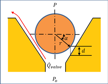
Figure 35.19 The oil flow rate through check valve
As the resistance of the oil through the check valve depends on the orifice area, in this investigation, the dynamic resistance is considered for the turbulent flow of the oil flow through the check valve, which yields,
\(\begin{aligned} & {{Q}_{valve}}={{C}_{d}}\cdot {{A}_{orifice}}\cdot \sqrt{\frac{2}{\rho }({{p}_{o}}-p)}(if,{{p}_{o}}\ge p) \\ & {{Q}_{valve}}=0(if,{{p}_{o}}<p) \\ \end{aligned}\)
- where,
- \({{p}_{o}}\) is the supply pressure.\(p\) is the chamber pressure.(If \({{p}_{o}}\) is less than \(p\), there is no oil flow through check valve.)\({{C}_{d}}\) is the discharge coefficient of check valve.\({{A}_{orifice}}\) is the orifice area.\(\rho\) is the density of oil.
\({{Q}_{valve}}\) represents the oil stream flowing rate through the opened check valve into the pressure chamber.
The area of orifice can be obtained such as
\({{A}_{orifice}}=min(\pi d\sin \alpha \cos \alpha (2r_b+d\sin \alpha ), \pi {{r_{co}^2}})\)
- where,
- \(d\) is the ball displacement.\(\alpha\) is the cylinder alpha.\(r_b\) is the ball radius.\({r}_{co}\) is the cylinder orifice radius.
35.2.2.1.3. The Oil Flow through the Leakage Gap
Since the pressure of chamber is different compared to the air pressure, the oil flow through the gap between the plunger and the cylinder is shown in Figure 35.20. The oil flowing between the plunger and the cylinder is a laminar flow.
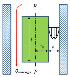
Figure 35.20 Oil flow and through the leakage gap
As shown in Figure 35.20, the variation of oil speed is fully depended on the pressure difference between the chamber and atmosphere, and it is not affected by the plunger speed. The oil flow rate between the gap of plunger and cylinder leakage can be written as
- where,
\(\mu\) is the coefficient of the viscosity of the oil.
35.2.2.1.4. The oil Flow through the Relief Valve
In order to calculate the oil flow through the relief valve, the static method is used in HAT Type B. The relief ball has no mass and no geometry, and the displacement of relief ball is defined as the next static equations. The oil flow through the relief valve can be calculated by the displacement of relief ball.
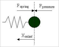
\(\begin{aligned} & {{A}_{relief}=max(\pi{{r}_{ro}^2},\pi{r}_{rb}^{2}{cos}^{2}\beta)} \\ & {{F}_{pressure}}=(p-{{p}_{o}})\cdot {{A}_{relief}} \\ & {{F}_{spring}}={{F}_{0}}+c\cdot {{X}_{relief}} \\ & {{X}_{relief}}=\frac{{{F}_{pressure}}-{{F}_{0}}}{c} \\ \end{aligned}\)
- where,
- \({{r}_{ro}}\) is the relief orifice radius.\({{r}_{rb}}\) is the relief ball radius.\(\beta\) is the relief seat angle.\({{A}_{relief}}\) is the ball section area.\(p\) is the chamber pressure.\({{p}_{o}}\) is the supply pressure.\({{F}_{0}}\) is preload of relief spring.\(c\) is stiffness coefficient of relief spring.\({{X}_{relief}}\) is displacement of relief ball and is limited between zero and maximum displacement of relief ball.
According as the relief ball moves to the calculated displacement by the upper equation, the relief valve opens or closes, and the oil flows. When the relief valve opens, the oil flow through the relief valve is shown in Figure 35.21.
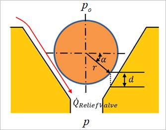
Figure 35.21 The oil flow rate through relief valve
As the resistance of the oil through the relief valve depends on the orifice area, in this investigation, the dynamic resistance is considered for the turbulent flow of the oil flow through the relief valve, which yields,
\(\begin{aligned} & {{Q}_{\operatorname{Re}liefValve}}={{C}_{d}}\cdot A_{ReliefValve}\cdot \sqrt{\frac{2}{\rho }({{p}_{o}}-p)}(if,{{p}_{o}}\ge p) \\ & {{Q}_{ReliefValve}}=0(if,{{p}_{o}}<p) \\ \end{aligned}\)
- where,
- \({{p}_{o}}\) is the supply pressure.\(p\) is the chamber pressure.(If \({{p}_{o}}\) is less than \(p\), there is no oil flow through relief valve.)\({{C}_{d}}\) is the discharge coefficient of relief valve.\(A_{ReliefValve}\) is the flow area of relief valve.\(\rho\) is the density of oil.
\({{Q}_{ReliefValve}}\) represents the oil stream flowing rate through the opened relief valve into the pressure chamber. The flow area of relief valve is obtained such as
\(A_{ReliefValve}=min(\pi {X}_{relief}\sin \beta \cos \beta (2{{r}_{rb}}+{X}_{relief}\sin \beta ),\pi{{r}_{ro}^2})\)
- where,
- \(\beta\) is the relief seat angle.\({r}_{rb}\) is the relief ball radius.\({r}_{ro}\) is the relief orifice radius.
35.2.2.1.5. Bulk Modules
The definition for the bulk modules is as follows:
The resulting bulk modulus of the oil - air mix is:
- where,
\({{r}_{air}}\) is the air volume fraction of the mix. The air and the oil states are calculated separately.
In isothermal case, assume that the bulk module of the air formulated as:
\({{E}_{air}}=p\)
In isentropic case, assume that the bulk module of air formulated as:
\({{E}_{air}}=kp\)
- where,
\(k\) is the ratio of specific heat.
Assume that the bulk modulus of oil formulated as:
\({{E}_{oil}}={{E}_{oil0}}+c(p-{{p}_{air}})\)
- where,
- \(c\) is the pressure coefficient\({{E}_{oil}}\) is the bulk modulus at the reference pressure
The air volume can be calculated as follows:
- where,
\(k\) is the ratio of specific heat.
The oil volume can be calculated as follows:
If \(c\ne 0\),
\[\begin{flalign} & {{V}_{oil}}=\frac{(1-{{r}_{air0}})V{}_{oil0}}{{{\left[ \frac{{{E}_{oil}}}{{{E}_{oil0}}} \right]}^{1/c}}} & \end{flalign}\]
If \(c=0\),
\[\begin{flalign} & {{V}_{oil}}=\frac{(1-{{r}_{air0}})V{}_{oil0}}{{{e}^{\left[ \frac{p-{{p}_{air}}}{{{E}_{oil0}}} \right]}}} & \end{flalign}\]
\({{r}_{air}}\) can be calculated as follows: