24.13.2. Event Sensor
The event sensor has a mother body, a center position, a range, and an event type. Event sensors are divided into two cases depending on what the sensing entity is. The sensing entity can be sheet or marker. Each case has 3 types of event sensors. The detail is as following table.
Sensing Entity |
Sensor Type |
Assembly (or Sheet) |
Head |
Tail |
|
On/Off |
|
Marker |
In |
Out |
|
On/Off |
Definition for Event Sensor with Assembly or a Sheet
The operation of Head type and Tail type event sensor is similar. The On/Off type is different with other sensors. Following table is shown sensing entity of each sensor type.
Sensor Type |
Sensing Entity |
Head |
Head of the sheet (or leading edge) |
Tail |
Tail of the sheet (or trailing edge) |
On/Off |
Sheet |
Head/Tail Type: The output of the each sensor is zero or one. Before the event occurs, the value is zero. After the event occurs, the value is one. The value of the Head type and Tail type sensor is still one, even though the head(tail) of sheet is passed the sensor range.
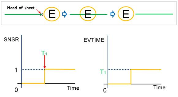
Figure 24.109 Event Sensor using head type
If the Sensing Entity is Assembly, the value of the sensor is accumulated one by one from zero and its event time is registered at each moment that the head or tail goes into the sensor about all sheets in assembly. Even though the counted sheet goes into the sensor, it is not sensed again.
On/Off Type: When the event occurs, the value of the On/Off type sensor is turned to one from zero. The value of sensor output is one when the sheet is exist in sensing range. Or not, the value is zero.
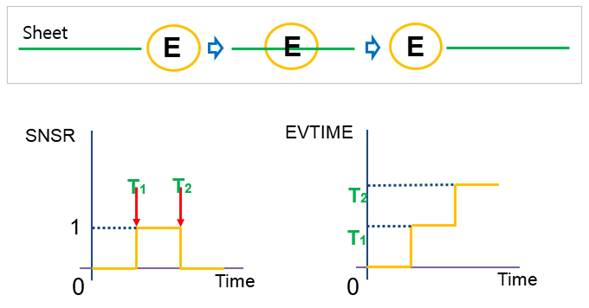
Figure 24.110 Event Sensor using On/Off type
If the On/Off type is selected, the event time is registered two times. The first time means beginning of event, second one is end of event. At the same time, output value is turned to zero.
Application
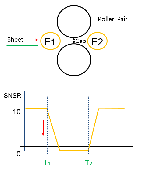
Figure 24.111 Application of Event Sensor
The roller and soft nip motion can be controlled by the event sensor with using the Function Expression of SNSR and EVTIME. For example, the gap of a roller pair as shown in Figure 24.111 can be controlled according to the plot shown in Figure 24.111. In this case, the soft nip motion is expressed by the following expression.
where, the sensor type of E1 is Head and the sensor type of E2 is Tail.
Definition for Event Sensor with a Marker
There are three types in the event sensor with a marker.
In Type: If the type of Head (IN) is selected, a value of the sensor is accumulated one by one from zero and its event time is registered at each moment that the specified marker goes into the sensor.
Out Type: If the type of Tail (OUT) is selected, a value of the sensor is accumulated one by one from zero and its event time is registered at the moment that the specified marker comes out from the sensor.
On/Off Type: The On/Off type is selected, the event time is registered two times when the marker goes to inside and goes to outside. The value of sensor output is one when the marker exists in sensing range. Or not, the value is zero.
24.13.2.1. Modeling Options
The user can create an event sensor as follows.
Point, Distance
Point: Selects a point on a body to define the center of event sensor.
Distance: Defines a range of region to measure output.
Body, Point, Distance
Body: Selects a body to define the parent body of event sensor.
Point: Selects a point on a body to define the center of event sensor.
Distance: Defines a range of region to measure output.
Body, Point, Distance, MultiMarker
Body: Selects a body to define the parent body of event sensor.
Point: Selects a point on a body to define the center of event sensor.
Distance: Defines a range of region to measure output.
MultiMarker: Selects a marker to define the event sensor with a marker. If it is defined, Use Marker option is checked automatically after creating the event sensor.
24.13.2.2. Properties
The properties dialog box of the Event Sensor has two tabs.
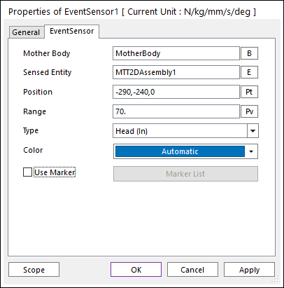
Figure 24.112 Event Sensor property page
Mother Body: Defines the body on which the Event Sensor is fixed.
Sensed Entity: Defines the sensed entity by the Event Sensor of MTT2D.
If MTT2DAssembly is set, all sheets defined in the assembly become a sensing target.
If a sheet body is set, only the sheet becomes a sensing target.
Position: Defines the center point of Event Sensor. The user can input this value as the Parametric Point.
Range: Defines the detecting range of Event Sensor. The user can input this value as the Parametric Value.
Use Marker: Allows the user to set markers for the Event Sensor. The “Add Markers” button in the Marker List dialog helps easily to select markers.
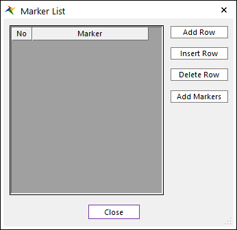
Marker List dialog for select markers
Add Row: Adds an empty row.
Insert Row: Inserts an empty row.
Delete Row: Deletes the selected rows.
Add Markers: Adds markers with mouse-drag on the view.
Type
When Use Marker is deactivated, the user can select three types as Head, Tail and On/Off. For more information, refer to Definition for EventSensor with Assembly or a Sheet.
When Use Marker”* is activated, the user can select three types as **IN, OUT and On/Off. For more information, refer to Definition for EventSensor with a Marker.
Color: Allows selecting the graphic color of Event Sensor.