32.3.2. Piston Liner Connector
A piston liner connector is defined with two bodies. This entity is created between a cylinder (an engine block) and a piston.
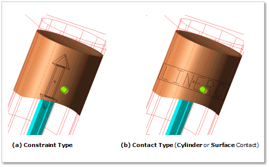
Figure 32.142 Piston Liner Connector
32.3.2.1. Modeling Options
Click the Liner icon of the Crank Connector group in the Crank tab. The user can see the Crank Component Liner Connector - Line Connector dialog box.
The user can choose the following types in Component Type and select the position where the constraint bearing is created in Component Index.
Constraint
Cylinder Contact
Surface Contact
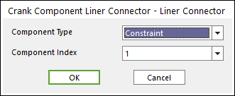
Figure 32.143 Crank Component Liner Connector - Liner Connector dialog box
Click OK.
32.3.2.2. Properties
The user can create the two kinds of liner connectors.
The first one is translational joint.
The other is contact liner connector (Cylinder or Surface contact).
32.3.2.2.1. Constraint Type of Liner connector
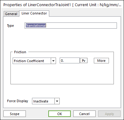
Figure 32.144 Liner Connector property page [Translational Joint]

32.3.2.2.2. Cylinder Contact Type of Liner Connector
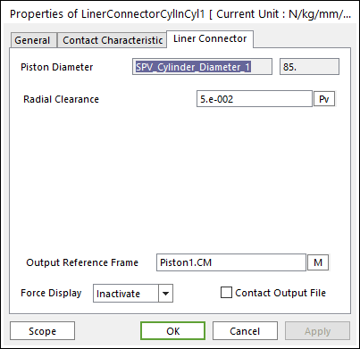
Figure 32.147 Liner Connector property page [Cylinder In Cylinder Contact]
Output Reference Frame: The user can choose another desired Reference Marker.
Contact Output File: If it is checked, the user can get specific output information file such as:
Table 32.2 Contact Output File Contents Variables
Descriptions
1
Time(sec)
Simulation Time
2
amount of contact point
Total number of calculated contact points
3
Pos_TX of Base Body CM
Position X of Center Marker for Base Body from Global
4
Pos_TY of Base Body CM
Position Y of Center Marker for Base Body from Global
5
Pos_TZ of Base Body CM
Position Z of Center Marker for Base Body from Global
6
Pos_PSI of Base Body CM
Position of Center Marker for Base Body in 3-1-3 Euler angle from Global
7
Pos_THETA of Base Body CM
Position of Center Marker for Base Body in 3-1-3 Euler angle from Global
8
Pos_PHI of Base Body CM
Position of Center Marker for Base Body in 3-1-3 Euler angle from Global
9
Pos_TX of Action Body CM
Position X of Center Marker for Action Body from Global
10
Pos_TY of Action Body CM
Position Y of Center Marker for Action Body from Global
11
Pos_TZ of Action Body CM
Position Z of Center Marker for Action Body from Global
12
Pos_PSI of Action Body CM
Position z-axis of Center Marker for Action Body in 3-1-3 Euler angle from Global
13
Pos_THETA of Action Body CM
Position x-axis angle of Center Marker for Action Body in 3-1-3 Euler angle from Global
14
Pos_PHI of Action Body CM
Position z-axis of Center Marker for Action Body in 3-1-3 Euler angle from Global
15
Global contact position
Position of Contact Points from Global
16
Contact position based on Base Body
Position of Contact Points from Base Body
17
Contact position based on Action Body
Position of Contact Points from Action Body
18
Contact force based on Action Body
Contact Force from Action Body
19
Friction force based on Action Body
Friction Force from Action Body
The user can see the output file in your working folder where your model is in. The output file name is Filename_ContactElementName.out.
Radial Clearance: Defines as a gap between the cylinder and piston.
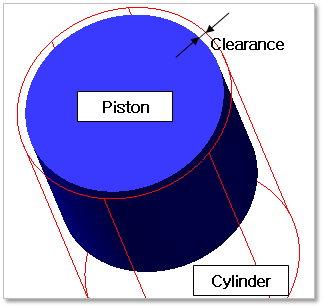
Figure 32.148 Definition of Clearance
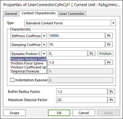
Figure 32.149 Contact Characteristic dialog box [Cylinder In Cylinder Contact]
Please refer to Type of Friction in below.
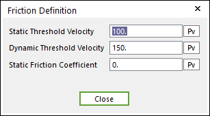
Standard Friction
Select Friction Coefficient in the combo box.
Click More and then values to define Coulomb Friction. For more information, click here.
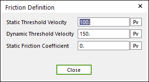
Figure 32.150 Friction Definition dialog box
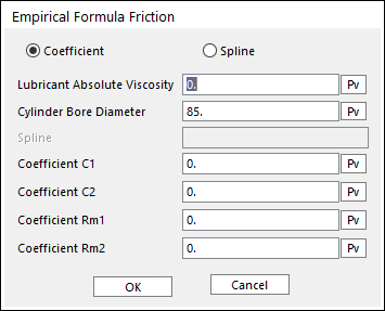
Empirical Formula (Refer to Constraint Bearing)
32.3.2.2.3. Surface Contact Type of Liner Connector
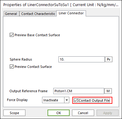
Figure 32.152 Liner Connector property page [Surface To Surface Contact]
Output Reference Frame: The user can choose another desired Reference Marker.
Contact Output File: If it is checked, the user can get specific output information file. For more information, click here.
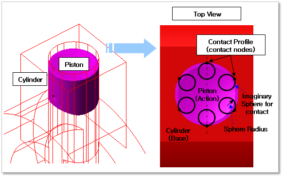
Figure 32.153 Properties of Surface Contact liner connector
Preview Contact Surface: The user can see the preview of defined contact surfaces. These surfaces are decided by Define Contact Profile on Piston and Define Cylinder Profile on Engine Block.
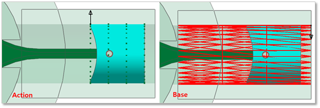
Figure 32.154 Preview Contact Surface

Figure 32.155 Liner Connector property page [Surface To Surface Contact]
Please refer to Type of Friction in below.
Standard Friction (refer to Bushing Bearing)
Select Friction Coefficient in combo box.
Click More and then values to define Coulomb Friction. For more information, click here.
Figure 32.156 Friction Definition dialog box
Empirical Formula (refer to Bushing Bearing)