6.7. Subsystem
A subsystem can be modeled, exported, and imported as one independent entity. The subsystem concept allows one to reutilize a set of entities which are contained in a subsystem. A system can have multiple levels of the subsystem.
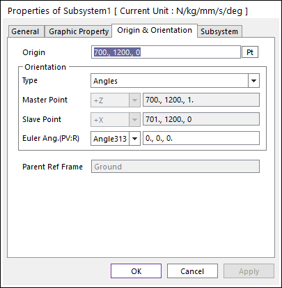
Figure 6.420 Subsystem dialog box
Subsystem page: Mother Body can be dispatched as other body by clicking Pt in the subsystem page.
Cut, Copy, and Paste commands in the subsystem mode are same as in the general mode. View, database, working plane management, object control in the subsystem mode are the same as in the general mode. A child subsystem is treated as one entity in cut, copy, and paste commands in its parent mode. The subsystem can use copy, paste and object control except the mirror.
6.7.1. Creating a New Subsystem
In order to create a subsystem, the mother part of subsystem must be outside of subsystem and cannot be accessed within subsystem. When a user creates a joint or force, its mother part may be the ground, or the mother part of subsystem, or one of subsystem bodies. A mother body of subsystem conformed by clicking the point. To exit child subsystem mode, click Exit on right-click menu or Exit icon of the Exit group in the Professional tab.
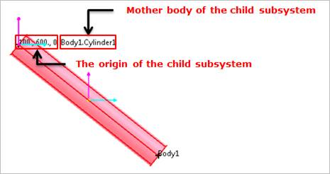
Figure 6.421 Mother body of Subsystem
Step to create a subsystem
Click the Subsystem icon of the Subsystem group in the Professional tab.
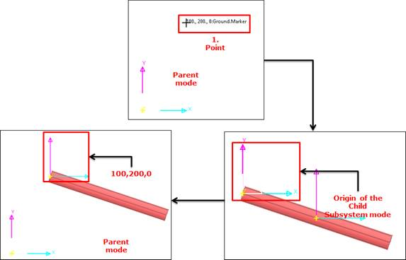
Figure 6.422 Subsystem creating mode
Click on a point, and the user can get in subsystem mode with an empty working plane. The point of the parent mode becomes the origin of child subsystem. The selected body becomes the mother body of child subsystem.
The subsystem origin point in the parent mode is located at the center of the working plane in child subsystem mode. The default name of a subsystem is SubSystem1.
Create entities as in a general RecurDyn model.
To return the parent system mode, click Exit on right-click menu or Exit icon of the Exit group in the Professional tab.
6.7.2. Creating a Joint or a Force
The user can create a joint or a force between the body and subsystem. A joint or a force can be attached between two subsystems. When creating a joint or a force between two subsystems, a joint or a force must be created while pressing Shift key.
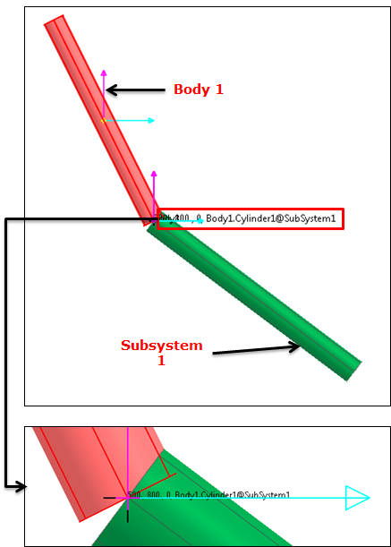
Figure 6.423 Creation of revolute joint
Step to create the revolute joint
Click icon in joint toolkit.
Press Shift key. Information of the connection of the revolute joint follows as.
500, 500, 0: The position of the revolute joint.
Body1@Subsystem1: Body1 : Base Body : Action Body
Click the point to create a joint or a force while pressing the Shift key.
Note
When the user presses the Shift Key, All of Marker and Icon in the subsystem are displayed. So, the user can easily find a target marker
6.7.3. Importing and Exporting of an Existing Subsystem
After a subsystem is created, the subsystem can be exported independently or as a part of a general RecurDyn model. The subsystem can be exported to a subsystem file in Child Subsystem Mode or to a model file in Parent Mode.
Step to export a subsystem as an independent entity
Choose Export in the menu bar of Child Subsystem Mode or Parent Mode.
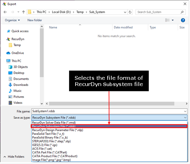
Figure 6.424 Export dialog box
Specify the file name.
Select export file format of RecurDyn Subsystem File (*.rdsb).
Click Save. A subsystem is exported to Filename.rdsb file.
Step to import an existing subsystem file
Choose Import in the menu bar of the Subsystem Mode or Assembly Mode.
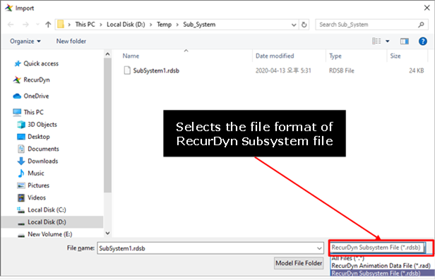
Figure 6.425 Import dialog box
Select export File format of RecurDyn Subsystem File (*.rdsb).
Click Open. A subsystem is imported.
6.7.4. Changing Layer for Internal Entity in Subsystem
When you want to change all the entity in the subsystem to the same layer, if using Internal Entity Layer function in property page for the subsystem, it is very useful.
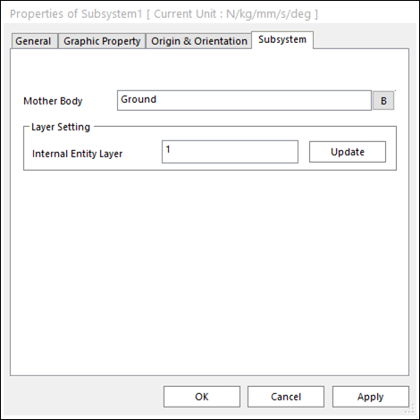
Figure 6.426 Property Page for subsystem
Step to Use
Open property page for the subsystem in Database Window.
Inputs a number in edit box for Internal Entity Layer.
Click Update. The layer numbers are changed.
6.7.5. Inactive flag of Subsystem
Specifies the active or inactive status of the subsystem. Like Body entity, the user can change active/inactive status of the subsystem on Database Window or Property Page.
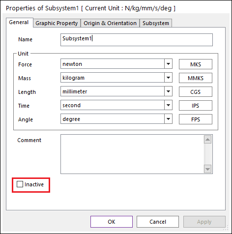
Figure 6.427 Inactive Flag in the Property Page
If the user changes the active/inactive status of a subsystem, all entities in the subsystem follows the active/inactive status of their parent subsystem. The inactive subsystem is displayed as grayed color like inactive bodies.
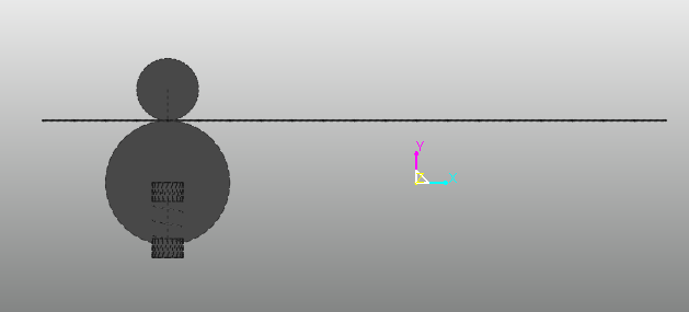
Figure 6.428 Inactive Subsystem on the working window
The user can activate or inactivate each entity in the subsystem, but the analysis follows the subsystem’s inactive flag. For example, if SubSystem1 is inactivated and Body1 in the SubSystem1 is activated, RecurDyn simulates without SubSystem1 and Body1.