20.6.9.3. PMSM (Permanent Magnet Synchronous Machine)
The PMSM block implements a 3-phases permanent magnet excited synchronous motor. This model assumes that the flux generated by the permanent magnets is sinusoidal, which implies that the electromotive forces are also sinusoidal. The DC machine block implements a series-connected or a shunt-connected DC motors.
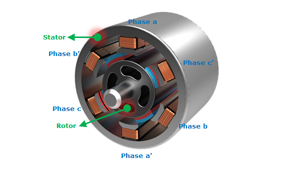
Figure 20.148 PMSM Motor
Dialog Box
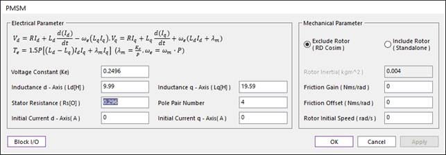
Figure 20.149 PMSM dialog box
Parameter Name |
Signal |
Description |
Voltage Constant |
\(K_e\) |
Voltage |
Stator Resistance |
\(T_s\) |
Stator resistance. [ohms] |
Inductance d-Axis |
\(L_d\) |
The d-Axis inductance. [H] |
Inductance q-Axis |
\(L_q\) |
The q-Axis Inductance. [H] |
Pole Pair Number |
The number of pole pairs. In Figure2, the value of Pairs of Poles is ‘4’. |
|
Initial Current d-Axis |
\(A\) |
Initial value of d-Axis current. |
Initial Current q-Axis |
\(A\) |
Initial value of q-Axis current. |
Parameter Name |
Signal |
Description |
Exclude Rotor / Include Rotor |
Select the type of Motor between Exclude Rotor and Include Rotor. The more detail explanation of two types is in the Equation of PMDC. |
|
Rotor Inertia |
\(J\) |
Inertia of rotor. This parameter don`t need on the Rotor Speed type. You can find the inertia of rotor in the datasheet. [kg*m^2] |
Friction Gain |
\(B\) |
Viscous friction gain between motor and load. When you apply the friction between the motor and the load in your dynamic model, you have to set this value to ‘0’. [Nms] |
Friction Offset |
\(T_f\) |
Viscous friction Offset between motor and load ( \(B\omega\) + offset). When you apply the friction between the motor and the load in your dynamic model, you have to set this value to ‘0’. [Nm] |
Rotor Initial Speed |
\(\omega\) |
Initial value of rotor speed. Set this value to ‘0’ if you don`t know it. [rad/s] |
20.6.9.3.1. Input and Output of PMSM
Exclude Rotor (RD Cosim) Type
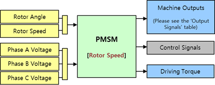
Figure 20.150 Input Port and Output Port of Rotor Speed Type
Port |
Input Signal |
Description |
|
1st Port |
Rotor Angle |
\(\theta\) |
The Rotor Angle. [rad] |
Rotor Speed |
\(\omega\) |
The Rotor Angular Speed. This value is a differential of Rotor Angl. [rad/s] |
|
2nd Port |
Phase A Voltage |
\(V_a\) |
The Phase A Voltage. [V] |
Phase B Voltage |
\(V_b\) |
The Phase B Voltage. [V] |
|
Phase C Voltage |
\(V_c\) |
The Phase C Voltage. [V] |
Port |
Output Signal |
Description |
|
1st Port |
Rotor Angle |
\(\theta\) |
The Rotor Angle. [rad] |
Rotor Speed |
\(\omega\) |
The Rotor Angular Speed. [rad/s] |
|
Stator Current of Phase A |
\(i_a\) |
The Stator Current of Phase A. [A] |
|
Stator Current of Phase B |
\(i_b\) |
The Stator Current of Phase B. [A] |
|
Stator Current of Phase C |
\(i_c\) |
The Stator Current of Phase C. [A] |
|
Stator Current of d-Axis |
\(i_{ds}\) |
The Stator Current of d-Axis. [A] |
|
Stator Current of q-Axis |
\(i_{qs}\) |
The Stator Current of q-Axis. [A] |
|
Stator Voltage of d-Axis |
\(V_d\) |
The Stator Voltage of d-Axis. [V] |
|
Stator Voltage of q-Axis |
\(V_q\) |
The Stator Voltage of q-Axis. [V] |
|
Electrical Torque |
\(T_e\) |
The Generated electrical torque. [N.m] |
|
2nd Port |
Control Signals |
This signal is used when you control the motor use the PMSM Drive block. When you use the PMSM Machine block, this port does npt export any signal. |
|
3rd Port |
Driving Torque |
\(T_d\) |
The driving torque \({{T}_{d}}\) subtracts the viscous friction of rotor from the electrical torque \({{T}_{e}}\). The more detail explanation of this is in the Rotor Speed part of the Equation of PMDC. [N.m] |
Example
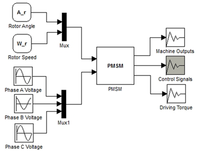
Figure 20.151 Example of Rotor Speed Type
Include Rotor (Standalone) Type
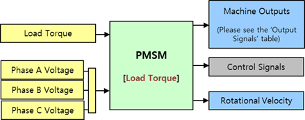
Figure 20.152 Input Port and Output Port of Load Torque Type
Port |
Input Signal |
Description |
|
1st Port |
Load Torque |
\(T_L\) |
The Load Torque. This value is used to calculate the Driving Torque in the Load Torque Type. [N] |
2nd Port |
Phase A Voltage |
\(V_a\) |
The Phase A Voltage. [V] |
Phase B Voltage |
\(V_b\) |
The Phase B Voltage. [V] |
|
Phase C Voltage |
\(V_c\) |
The Phase C Voltage. [V] |
Port |
Output Signal |
Description |
|
1st Port |
Rotor Angle |
\(\theta\) |
The Rotor Angle. [rad] |
Rotor Speed |
\(\omega\) |
The Rotor Angular Speed. [rad/s] |
|
Stator Current of Phase A |
\(i_a\) |
The Stator Current of Phase A. [A] |
|
Stator Current of Phase B |
\(i_b\) |
The Stator Current of Phase B. [A] |
|
Stator Current of Phase C |
\(i_c\) |
The Stator Current of Phase C. [A] |
|
Stator Current of d-Axis |
\(i_{ds}\) |
The Stator Current of d-Axis. [A] |
|
Stator Current of q-Axis |
\(i_{qs}\) |
The Stator Current of q-Axis. [A] |
|
Stator Voltage of d-Axis |
\(V_d\) |
The Stator Voltage of d-Axis. [V] |
|
Stator Voltage of q-Axis |
\(V_q\) |
The Stator Voltage of q-Axis. [V] |
|
Electrical Torque |
\(T_e\) |
The Generated electrical torque. [N.m] |
|
2nd Port |
Control Signals |
This signal is used when you control the motor use the PMSM Driver block. When you use the PMSM Machine block, this port does not export any signal. |
|
3rd Port |
Rotational Velocity |
Rotor Rotational Velocity. [rad/s] |
Example
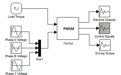
Figure 20.153 Example of Load Torque Type
20.6.9.3.2. Equation of PMSM
Electrical Part
The voltage balance equation is as follows.
\(\begin{aligned} & {{V}_{d}}={{L}_{d}}\frac{d{{I}_{d}}}{dt}+R{{i}_{d}}-p{{\omega }_{m}}{{L}_{q}}{{i}_{q}} \\ & {{V}_{q}}={{L}_{q}}\frac{d{{I}_{q}}}{dt}+R{{i}_{q}}+p{{\omega }_{m}}{{\varphi }_{m}}+p{{\omega }_{m}}{{L}_{d}}{{i}_{d}} \\ & {{T}_{e}}=1.5p\left[ {{\varphi }_{m}}{{i}_{q}}+({{L}_{d}}-{{L}_{q}}){{i}_{d}}{{i}_{q}} \right] \\ \end{aligned}\)
where the variables means:
Variables |
Description |
\(V_d\) |
d-axis voltage |
\(V_q\) |
q-axis voltage |
\(i_d\) |
d-axis current |
\(i_q\) |
q-axis current |
\(L_d\) |
d-axis inductance |
\(L_q\) |
q-axis inductance |
\(R\) |
Resistance of stator windings |
\(\omega_m\) |
Angular velocity of the rotor |
\(\varphi\) |
Flux induced by the permanent magnets |
Mechanical Part
For more information, refer to Equation of PMDC.