30.2.2. Roller Sprocket
The chain converts rotational power to pulling power, or pulling power to rotational power, by engaging with the sprocket. In general, a chain system employs single sprocket consisted of teeth and the main body named sprocket hub. Exact sprocket tooth geometry must be defined. The sprocket tooth geometry data can be created, edited, exported or imported from a predefined data file.
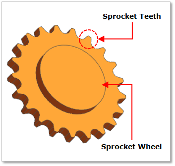
Figure 30.12 Sprocket geometry
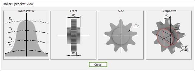
Figure 30.13 Sprocket dimension information
Wt |
Width of Teeth |
Rw |
Sprocket Wheel Radius |
Ww |
Width between Wheels |
Rd |
Dedendum Circle Radius |
Rb |
Base Circle Radius |
Rp |
Pitch Circle Radius |
Ra |
Addendum Circle Radius |
30.2.2.1. Modeling Options
The user can create a sprocket as follows.
Point, WithDialog
Point: Selects a point to define the center of the sprocket.
WithDialog: Modifies the property for the sprocket. The sprocket is created with clicking OK.
30.2.2.2. Properties
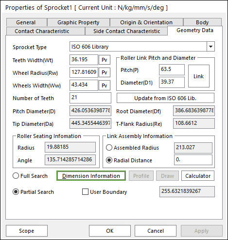
Figure 30.14 Sprocket property page [Geometry Data page]
The Sprocket property page is shown in Figure 30.14. The parameters are explained below.
Sprocket Type: General type, ISO 606 Library type and Parameters type are supported in RecurDyn/Chain.
Teeth Width(Wt): Enters the teeth width of sprocket.
Wheel Radius(Rw): Enters the wheel radius of sprocket.
Wheels Width(Ww): Enters the wheel width of sprocket.
Number of Teeth: Enters the number of teeth.
Link Assembly Information: The gap between link pins and sprocket teeth can be controlled by Assembled Radius or Radial Distance.
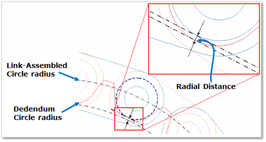
Figure 30.15 Sprocket tooth profile
Full Search: All links are searched for contact.
Partial Search: Some links are searched for contact in some boundary. It is used to reduce total solving time.
User Boundary: In the case of Partial Search, the search boundary can be modified.
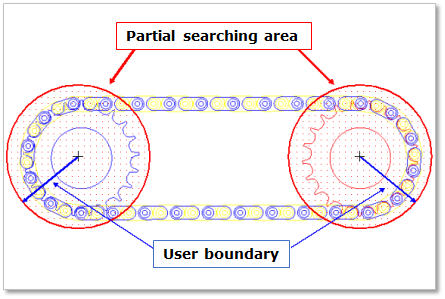
Figure 30.16 Partial searching area & user boundary
30.2.2.2.1. Sprocket Type
General Sprocket Type
General type defines the shape of the sprocket using mainly profile.
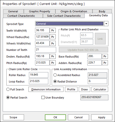
Figure 30.17 Sprocket property page [Geometry Data page]
In order to understand the geometry, refer to Dimension Information.
Deden. Radius: Enters the dedendum circle radius of tooth profile.
Pitch Radius: Enters the pitch circle radius of tooth profile.
Base Radius: Enters the base circle radius of tooth profile.
Adden. Radius: Enters the addendum circle radius of tooth profile.
Profile
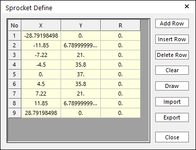
Figure 30.18 Sprocket Define dialog box
X,Y,R: Points and radius.
Add Row: Adds a row to the end of the table.
Insert Row: Inserts a row where the cursor is and move the current and later rows down.
Delete Row: Deletes the row where the cursor is and move the later rows up.
Clear: Deletes all rows in the table.
Draw: All data must be defined with respect to the sprocket tooth marker. You can move points graphically by using the mouse directly.
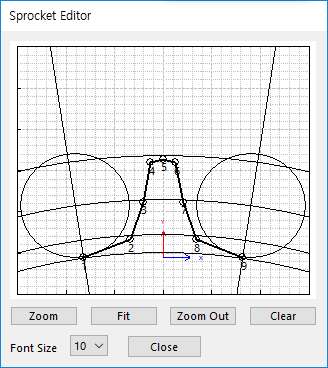
Figure 30.19 Sprocket Editor dialog box
Import: Imports the X, Y, and R data pairs from a CSV file or a MAT file or a text file. In the case of the text file, the usage of the comma, the tab, and the space can be the delimiter between the three columns in the file. And when using the Excel file, the user can select the Tab-delimited text file output option or the CSV (Comma-Separated Values) file output option to save the Excel file which can be imported.
Export: Exports the X, Y, and R data pairs to a CSV file or a MAT file or a text file.
Chain Link Roller Circle
All data must be defined with respect to the sprocket tooth marker. Users can easily modify relation of between sprockets and rollers using Roller Radius and Loop Radius
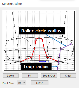
Figure 30.20 Sprocket Editor dialog box
ISO 606 Sprocket Type
ISO 606 type defines the shape of the sprocket in the ISO standard.
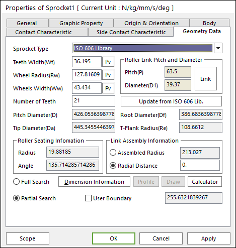
Figure 30.21 Sprocket property page [Geometry Data page]
Roller Link Pitch and Diameter
The shape of the sprocket is calculated from the link navigated or re-calculated on the basis of the parameters that have changed by clicking Update from ISO 606 Lib.
Pitch Diameter(D): Shows the pitch diameter calculated as the following question.
Tip Diameter(Da): Shows the tip diameter calculated as the following question.
Root Diameter(Df): Shows the root diameter calculated as the following question.
T-Flank Radius(Re): Shows the T-Flank radius calculated as the following question.
Roller Seating Information
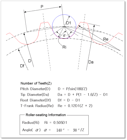
Figure 30.22 Tooth gap Forms
Parameters Sprocket Type
Parameters type defines the shape of the sprocket from each parameter. The parameters are same with ISO 606 Sprocket Type. For more information, click here.
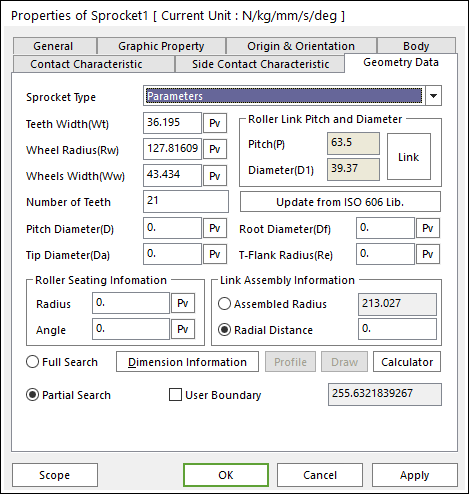
Figure 30.23 Sprocket property page [Geometry Data page]
Contact between a Sprocket and a Link
The sprocket is in contacts with the chain link in the two parts.
The sprocket teeth surface – the roller of chain link
The sprocket teeth surface - the inner plate surface of chain link
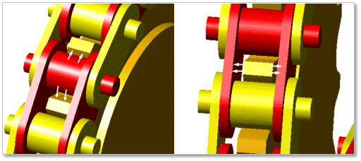
Figure 30.24 Contact between a sprocket and chain links