6.1.4.1.1. Marker
A marker is the local coordinate system included in a body. So, in Body Edit Mode, the user makes a marker using the Marker icon in the Solid and Marker group, and it is possible to modify the position and the orientation of the generated marker in the Marker property page.
6.1.4.1.1.1. Modeling Options
The user can create a marker by the following procedure.
Point
Point: Selects a point to define the position of the marker. The orientation of the marker is the same as the working plane.
Point, Point
Point: Selects a first point to define the position of the marker.
Point: Selects a second point to define the position of the marker. The marker is created at the center position between two points.
Point, Direction, Direction
Point: Selects a point to define the position of the marker.
Direction: Defines the direction of the Z-axis of the marker.
Direction: Defines the direction of the X-axis of the marker.
Curve, WithDialog
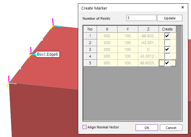
Figure 6.29 Preview for Create Marker
Curve: Selects a curve. And then, the N division points of the selected curve are displayed with the Create Marker dialog box.
WithDialog: Selects points to create markers in Create Marker dialog box. And then the markers are created by clicking OK.
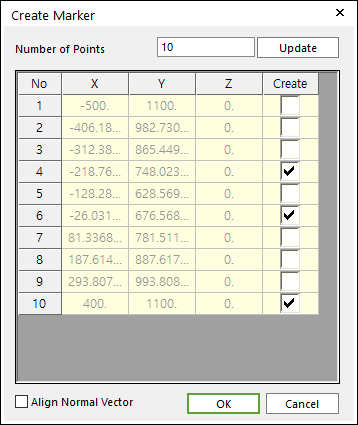
Figure 6.30 Create Marker dialog box
Number of Points: Inputs the value for division and clicks Update.
Create: Checks the check boxes in the Create column and clicks OK.
Align Normal Vector: If this option is checked, in order to make the Z axis of generating markers align to the normal direction of the selected curve, the orientation of the markers is changed.
Solid(Surface, Curve), Solid(Surface, Curve), Predefined Point
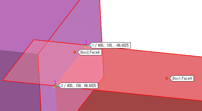
Figure 6.31 Preview for Predefined Points
Solid(Surface, Curve): Select a solid, surface, or curve geometry to find intersection points.
Solid(Surface, Curve): Select a solid, surface, or curve geometry to find intersection points. And then the user can see intersection points between two geometries on Working Window.
Predefined Point: Select a point among the displayed intersection points on Working Window.