6.2.2.4. Screw
A screw joint can define the rotation of one part about an axis as the part translates along the axis with respect to the other part. It does not need that the two parts remain parallel with respect to the axis of rotation and translation. The defined axis by two points becomes the z-axes of the base marker and action marker. It becomes the axis of rotation and translation. However, the z-axis of the coordinate system marker on the first part and the z-axis of the coordinate system marker on the second part must always be parallel and co-directed. This joint has one degree of freedom. The translation of the z-axis is constrained by a pitch about the rotational degree of freedom. The pitch value is the distance from one peak on a thread of the screw to the next thread. It defines the amount of translational displacement of the first part for every rotation of the second part about the axis of rotation.
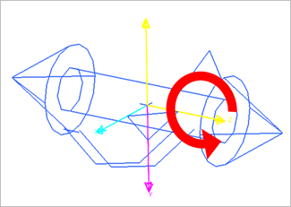
Figure 6.168 Screw Joint icon on Working Window
6.2.2.4.1. Modeling Options
The user can create a joint entity as follows.
Point, Direction
Point: Selects a point on two bodies to define the location of the screw joint.
Direction: Defines the direction of z-axes of base and action markers as the axis of translation and rotation. The translation displacement and rotation angle are related by pitch.
Point, Direction, Distance
Point: Selects a point on two bodies to define the location of the screw joint.
Direction: Defines the direction of z-axes of base and action markers as the axis of translation and rotation. The translation displacement and rotation angle are related by pitch.
Distance: Defines the pitch.
Body, Body, Point, Direction
Body: Selects a base body of the screw joint.
Body: Selects an action body of the screw joint.
Point: Selects a point on two bodies to define the location of the screw joint.
Direction: Defines the direction of z-axes of base and action markers as the axis of translation and rotation. The translation displacement and rotation angle are related by pitch.
Body, Body, Point, Direction, Distance
Body: Selects a base body of the screw joint.
Body: Selects an action body of the screw joint.
Point: Selects a point on two bodies to define the location of screw joint.
Direction: Defines the direction of z-axes of base and action markers as the axis of translation and rotation. The translation displacement and rotation angle are related by pitch.
Distance: Defines the pitch.
6.2.2.4.2. Properties
The user can define the force display and the value of pitch using the Joint page.
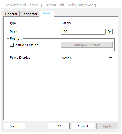
Figure 6.169 Screw property page [Joint page]
Type: Shows the type of joint.
Pitch: Moves the position up to pitch value per one revolution along the z-axis.
Include Friction: If this option is checked, the friction force can be defined for the screw joint.
Force Display: Displays the resultant force vector graphically on Working Window.
6.2.2.4.2.1. Joint Friction
A friction force that contains a sliding and stiction algorithm can be defined on the screw joint. Include Friction option in Joint property page must be checked to use the friction force.
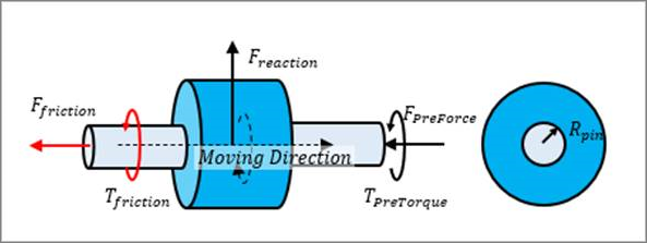
Figure 6.170 Configuration of Sliding and Stiction Friction Force on Screw Joint
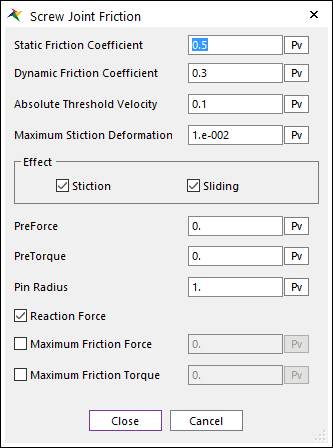
Figure 6.171 Screw Joint Friction dialog box
The frictional force and torque are calculated according to the following equations:
\(\begin{aligned} & {{F}_{friction}}=\mu ({{F}_{reaction}}+(1/{{\mu }_{s}}){{F}_{preForce}}) \\ & {{T}_{friction}}=\mu ({{R}_{pin}}{{F}_{reaction}}+({{R}_{pin}}/{{\mu }_{s}}){{F}_{preForce}}+(1/{{\mu }_{s}}){{T}_{preTorque}}) \\ \end{aligned}\)
Where, the inputs into the equation are defined in the following table:
Current Friction Coefficient |
\(\mu\) |
The coefficient of friction calculated during the simulation is a function of the relative velocity between body surfaces. |
Static Friction Coefficient |
\({{\mu }_{s}}\) |
The coefficient of friction is zero at a zero velocity, but it smoothly transitions to the static coefficient of friction at Absolute Threshold Velocity (\(\Delta v\)). |
Effect |
Checks Stiction or Sliding.
\({{\mu }^{sliding\text{ }only}}=-{{\mu }_{v}},\text{ }{{\mu }_{v}}^{\max }={{\mu }_{d}}\)
\({{\mu }^{stiction\text{ }only}}=-\left( 1-\beta \right){{\mu }_{\delta }}-{{\mu }_{v}},\text{ }{{\mu }_{v}}^{\max }={{\mu }_{s}}\)
For more information, click here.
|
|
Pre Force |
\({{F}_{preload}}\) |
A constant frictional force that acts during the entire simulation. |
Pre Torque |
\({{T}_{preload}}\) |
A constant frictional torque that acts during the entire simulation. |
Pin Radius |
\({{R}_{pin}}\) |
The radius of the smaller surface geometry in the revolute joint. |
Reaction Force |
\({{F}_{reaction}}\) |
The force in the joint calculated during the simulation in the direction along the rotational axis. |
Maximum Friction Force |
\({{F}_{\max }}\) |
Collisions during contact as well as transitions during sliding forces can result in force spikes. High frictional forces can result from these spikes. This option allows a maximum friction force to be defined that should correspond to the maximum expected steady-state force. |
Maximum Friction Torque |
\({{T}_{\max }}\) |
Collisions during contact as well as transitions during sliding forces can result in force spikes. High frictional torques can result from these spikes. This option allows a maximum friction torque to be defined that should correspond to the maximum expected steady-state force. |