27.3.2.2. Contact Parameter between Soil Ground and Shoe
If Pressure-Sinkage is checked, contact parameters between the ground and track link shoe is changed as soil conditions. 6 parameters are used to describe soil conditions.
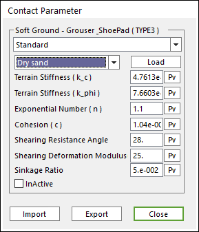
Figure 27.56 Contact parameter between soft ground and track link shoe
Pressure-sinkage (Bekker’s theory) relationship is described as the following equation proposed by Bekker:
\(p=\left( \frac{k{}_{c}}{b}+{{k}_{\phi }} \right){{z}^{n}}\)
Where, \(p\) is pressure, \(b\) is the smaller dimension of the contact patch, that is, the width of a rectangular contact area, \(z\) is sinkage, and \(n\), \(k{}_{c}\), and \(k{}_{\phi }\) are pressure-sinkage parameters.
Repetitive normal load of a terrain can be considered as shown in the Figure 27.56 because a terrain element is subject to the repetitive loading of the wheels of a tracked vehicle. The range between unloading and reloading can be approximated by a linear function in the pressure-sinkage relationship.
\(p(z)={{p}_{u}}-{{k}_{u}}({{z}_{u}}-z)\)
where, \(p\) and \(z\) are the pressure and sinkage, respectively, during unloading or reloading; \({{p}_{u}}\) and \({{z}_{u}}\) are the pressure and sinkage, respectively, when unloading begins; and \({{k}_{u}}\) is the average slope of the unloading-reloading line.
\({{k}_{u}}=\frac{{{p}_{u}}}{({{z}_{u}}*{{r}_{s}})}\)
where, \({{r}_{s}}\) is sinkage ratio
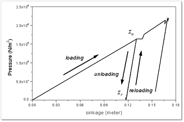
Figure 27.57 Response to repetitive normal load
Shear stress-shear displacement relationship is described by an exponential function of the following form proposed by Janosi and Hanamoto:
\(\tau =(c+p\tan \phi )(1-{{e}^{-j/K}})\)
where, \(\tau\) is the shear stress, \(j\) is the shear displacement, \(c\) and \(\phi\) are the cohesion and the angle of internal shearing resistance of the terrain, respectively, and \(K\) is referred to as the shear deformation modulus.
27.3.2.2.1. Track_Soil_Subroutine
The contact parameter between soil ground and shoe pad can be defined by User Subroutine.
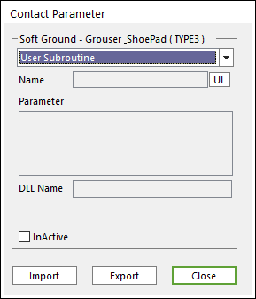
Figure 27.58 TYPE3 in Contact Parameter dialog box
This subroutine generates a user defined soil force.
Language type |
track_soil_force subroutine |
Fortran |
track_soil_force (time, info, upar, npar, dird, dirv, disp, lgori, ngpos, ngori, ngvel, length, width, iflag, result) |
C/C++ |
track_soil_force (double time, int info[], double upar[], int npar, double dird[],double dirv[], double disp[], lgori[], double ngpos[], double ngori[],double ngvel[], double length, double width, int iflag, double result[3]) |
Parameter information is as follows.
time: Current simulation time of RD/Solver
info: ID of body & node
upar: Argument list array
npar: Number of arguments in the argument list array
dird: Direction vector of a ground patch
dirv: Velocity of a contact node relative to direction vector
disp: Sinkage & shear displacements
lgori: Global orientation of a track link.
ngpos: Global position of a contact node
ngori: Global orientation of a contact node
ngvel: Global velocity of a contact node
length: Length of meshed rectangle at a track link
width: Width of meshed rectangle at a track link
iflag: When RD/Solver makes an initial call, the flag is true (-1)
result: Returned force vector and three-dimensional array
Example
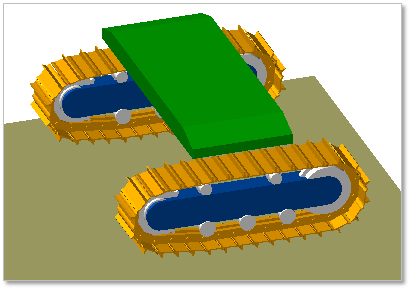
Figure 27.59 Track vehicle model using track soil user subroutine
To see code about example, refer to TRACK_SOIL_FORCE.