6.1.4.6. Boolean
In the Boolean group, the user can operate the specific actions by using Unite, Subtract, and Intersect.
6.1.4.6.1. Unite
It allows the user to combine two geometric entities in order to create a single and combined geometric entity. This function makes the second part merge into the first part. For reference, the mass and the moments of inertia of the united body are calculated automatically.
Modeling Options
The user can work the unite operation for two geometric entities by the following procedure.
Solid, Solid
Solid: Selects a solid geometry.
Solid: Selects a solid geometry.
Solid, MultiSolid
Solid: Selects a solid geometry.
MultiSolid: Selects several solid geometries. All selected solid geometries are united.
Difference between Unite Operation and Merge Body
The united body is calculated correctly for the mass of the overlapped part between bodies. However, in the case of a merged body, the mass properties are just summed with each body’s mass property.
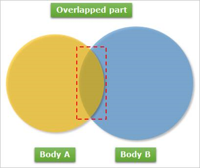
Figure 6.103 Overlapped part between Body A and Body B
Additionally, when the user merged a sphere or a cylinder created by RecurDyn, it is possible to apply the primitive contact. However, in the case of the united body, only general contact should be used.
6.1.4.6.2. Subtract
It allows the user to create a new geometric entity by removing the interference section between two entities from the original geometric entity. For reference, the mass and the moments of inertia of the subtracted body are calculated automatically.
Modeling Options
The user can work the subtract operation for two geometric entities by the following procedure.
Solid, Solid
Solid: Selects a solid geometry to be modified.
Solid: Selects a solid geometry to subtract from the first selected one.
Solid, MultiSolid
Solid: Selects a solid geometry.
MultiSolid: Selects several solid geometries to subtract from the first selected one.
6.1.4.6.3. Intersect
It allows the user to define the interference section between two geometric entities as a new geometric entity.
Modeling Options
The user can work intersect operation for two geometric entities by the following procedure.
Solid, Solid
Solid: Selects a solid geometry.
Solid: Selects a solid geometry that interfered with the first selected one.
Solid, MultiSolid
Solid: Selects a solid geometry.
MultiSolid: Selects several solid geometries that interfered with the first selected one.
6.1.4.6.4. Step to Redefine Boolean Operation or Local Operation
The user can redefine the Boolean operation or the Local operation. After the Boolean operation or the Local operation, each Boolean Local operation is created in the form of CSG Tree.
CSG(Constructive Solid Geometry) Tree
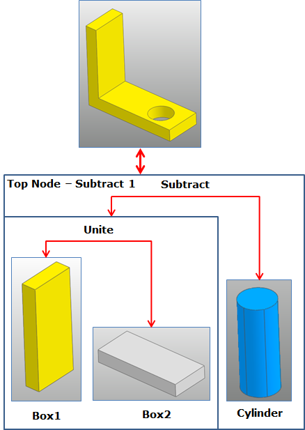
Figure 6.104 CGS Tree
Step to redefine the Boolean Operation
Click the right mouse button in the Database Window.
Select Delete Top Node Only.
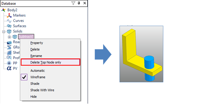
Figure 6.105 Delete the Top Node of the CGS tree
Modify geometric entities.
Redefine the Boolean operation.
6.1.4.6.5. Properties for Hierarchy
The property page shows the Boolean operation hierarchy. In the page sub-geometries of Boolean operation can be swapped with other geometry in the body edit mode. The properties of sub-geometries can be modified.
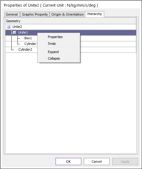
Figure 6.106 Property page of Boolean [Hierarchy page]
Context Menu
Properties: The properties pages of the sub-geometry of the Boolean operation is open.
Swap: Select another geometry, then the original sub-geometry of the Boolean operation is swapped with the new geometry.