6.2.3.8. Cartesian Motion Group (CMotion Group)
A CMotion group is the group of 6 CMotion Joints. Each CMotion Joint in a group has fixed Cartesian Motion Type - X, Y, Z and RX, RY, RZ. And every CMotion Joint shares the same action and base entity, also ref. marker and Force Display type. But the initial condition - Displacement, Velocity, and Acceleration can be varied.
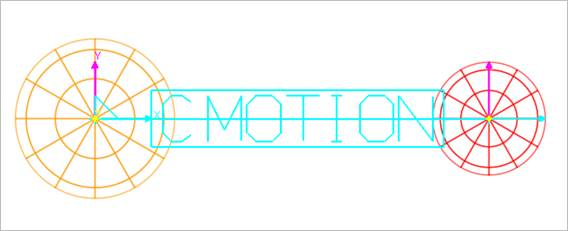
Figure 6.220 CMOTION Group (Cartesian Motion Group) icon on Working Window
6.2.3.8.1. Modeling Options
The user can create a joint group entity as follows.
Point, Point
Point: Selects a point on a base body.
Point: Selects a point on an action body.
Body, Body, Point, Point
Body: Selects a base body of the cmotion joint.
Body: Selects an action body of the cmotion joint.
Point: Selects a point.
Point: Selects a point.
6.2.3.8.2. Properties
The user can define initial conditions using the CMotion Group page. For more information about CMotion, click here. CMotion and CMotion Group using Euler 321 for rotation. Euler 321 has a singular angle in 90, 270… degree of RY, but CMotion Group can rotate the singular angle by using all rotation component RX, RY and RZ. (If the user uses single and double component for rotation, the singular problem has occurred in the specific angle.)
The user can define the motion and initial condition of all DOF (Translational and Rotational) in one dialog.
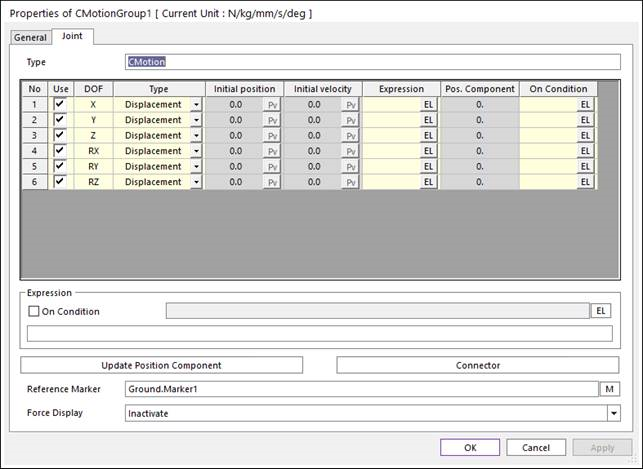
Figure 6.221 CMOTION property page [Joint page]
There are 6 columns for each DOF and 9 rows for properties.
No: The Column number.
Use: If checked, active this DOF. If the checkbox for RX, RY, RZ are all checked, the singular angle can be used.
DOF: Column to separate each DOF. This column cannot be changed.
Type: Define the Cmotion type. There are 3 types. Displacement, Velocity, Acceleration.
Initial position: Define the initial position when the type is velocity or acceleration.
Initial velocity: Define the initial velocity when the type is acceleration.
Expression: Define the expression for motion of this DOF.
Pos. Component: The displacement of two markers. These two markers are action marker and base marker. The information for both markers can be found on the connector page.
On Condition.: Define the expression for On/Off. It is an expression to control only this DOF.
There are 5 sections at the bottom area.
Expression: This section is for expression to control On or Off the Cmotion group. If the expression value is not equal to zero, Cmotion is ON.
Update Position Component: Reloads the displacement of two markers in Pos. Component columns.
Connector: Shows the base and the action property page of joints. This page is different from its other joints. The name of the base and action markers cannot be changed.
Reference Marker: Define the reference marker for Cmotion Joint.
Force Display: Displays the resultant force vector graphically on Working Window.