6.4.2.8. Cylinder To Surface
A Cylinder To Surface Contact generates a force between a cylinder and surface. The base surface has a RM and many points. The action cylinder has a RM and its radius and length. The base curve is parameterized from many points and creates a contact curve fitted on a cubic spline.
The cylinder and surface must belong to two different bodies.
The contact force can be generated with not only linear or exponential but also nonlinear spline characteristics to the contact penetration and its velocity.
The base surface is approximated as multi triangular patches as shown in Figure 6.350.
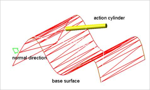
Figure 6.350 Cylinder and surface
6.4.2.8.1. Modeling Options
In the case of Cylinder To Surface contact, a cylinder geometry type is supported for an action geometry and surface geometry type is supported for a base geometry when creating.
Surface, Cylinder
Surface: Selects a surface to define a base surface.
Cylinder: Selects a cylinder to define an action cylinder.
Surface, MultiCylinder
Surface: Selects a surface to define a base surface.
MultiCylinder: Selects some cylinders to define action cylinders.
Surface, Cylinder, Surface, Cylinder
Surface: Selects a surface to define a base surface.
Cylinder: Selects a cylinder to define an action cylinder.
Surface: Selects a surface to define another base surface.
Cylinder: Selects a cylinder to define another action cylinder.
MultiSurface, MultiCylinder
MultiSurface: Selects some surfaces to define base surfaces.
MultiCylinder: Selects some cylinders to define action cylinders.
Solid(Shell), Cylinder
Solid(Shell): Selects a solid or a shell to define a base surface.
Cylinder: Selects a cylinder to define an action cylinder.
Solid(Shell), MultiCylinder
Solid(Shell): Selects a solid or a shell to define a base surface.
MultiCylinder: Selects some cylinders to define action cylinders.
Solid(Shell), Cylinder, Solid(Shell), Cylinder
Solid(Shell): Selects a solid or a shell to define a base surface.
Cylinder: Selects a cylinder to define an action cylinder.
Solid(Shell): Selects a solid or a shell to define another base surface.
Cylinder: Selects a cylinder to define another action cylinder.
MultiSolid(Shell), MultiCylinder
MultiSolid(Shell): Selects some solid or shells to define base solids.
MultiCylinder: Selects some cylinders to define action cylinders.
6.4.2.8.2. Properties
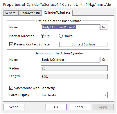
Figure 6.351 Properties of CylinderToSurface dialog box
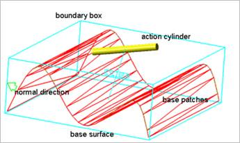
Figure 6.352 Preview of the normal directions, contact patches and boundary box
Definition of The Base Surface
Entity Name: Defines the name of base surface. The base surface can be dispatched from the Working Window by clicking Gr.
Normal Direction: Defines the normal direction of a base surface for a contact as shown in Figure 6.352.
The contact is available in the specified direction.
As selecting Up or Down, the user can change the contact direction of a base surface.
If this page is activated, the normal direction is automatically shown on the Working Window
Preview Contact Surface: If this button is checked, the patches making the contact surface and its boundary box are shown on the Working Window as shown.
Contact Surface: Accesses the Contact Surface dialog box. For more information, click here.
Definition of The Action Cylinder
Entity Name: Defines the name of action cylinder. The action cylinder can be dispatched from the Working Window by clicking Gr.
Radius: Shows the radius of action cylinder.
Length: Shows the length of action cylinder.
Synchronize with Geometry
If this option is checked, Radius and Length in contact properties are automatically defined with that of the specified graphics. (The default is checked)
If this option is not checked, the user can modify the contact properties.
Force Display: Graphically displays the resultant force vector on the view window.