31.1.11. Worm Gear
A worm gear is used for transmitting power between two non-parallel and non-intersecting shafts. It is useful when a large speed reduction ration is required between crossed axis shafts. A worm is similar to a screw and a worm gear is similar to a nut. Therefore, if the worm is rotated, the worm gear can be caused to rotate due to the screw like action of the worm.
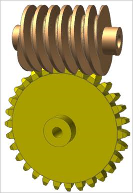
Figure 31.60 Worm & Worm Gear system
Worm & worm gear are composed of a single body. Gear geometries are created from the parameters of ISO standards. The tooth profile is represented by multiple arcs. The sprocket tooth geometry data is:
Created from a predefined data file
Edited from a predefined data file
Exported from a predefined data file
Imported from a predefined data file
Terminology
Worm Gear has a pitch diameter at the center point of the wrap-around curve. It has parts similar to a spur gear except for one, which is called Throat Diameter as shown in Figure 31.61. And Pitch Diameter is calculated the same as for spur gears.

Figure 31.61 Worm Gear Terminology
Circular Pitch (Pc) of a worm gear is a distance measured along the pitch circle of the gear. It can be determined by measuring the distance between any two corresponding points of adjacent teeth as shown above. In order to calculate this parameter, the axial module (ma) should be used, which can be calculated as the following relation. For reference, the normal module (mn) is the input value in the module of worm dialog box.
Throat Diameter (Dt) has the following relation with Pitch Diameter (D) and Addendum.
Pitch Diameter (D) has the following relation with Normal Module (mn), the number of teeth (z) and Lead Angle (γ).
Addendum has the following relation with Addendum Factor (Fa) and Addendum Modification Coefficient (x)
For more information, refer to Geometric Entities.
31.1.11.1. Properties
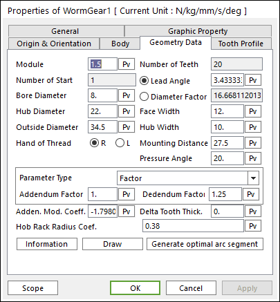
Figure 31.62 Worm Gear property page [Geometry Data page]
The Worm Gear property page is shown in Figure 31.62. The parameters are explained below.
Module: Enters the module of the gear.
Number of Teeth: Enters the number of teeth. The maximum number of teeth of gear is 400.
Lead Angle: Enters the lead angle of worm gear. This can define a pitch diameter. For more information, click here.
Diameter Factor: Enter the factor for Pitch Diameter. This can define a pitch diameter and lead angle. For more information, click here.
Bore Diameter: Enters the bore diameter of worm gear.
Hub Diameter: Enters the hub diameter of worm gear.
Face Width: Enters the face width of worm gear.
Outside Diameter: Enters the outside diameter of worm gear.
Hub Width: Enters the hub width of worm gear.
Hand of Thread: Defines the direction of thread as L or R.
Mounting Distance: Shows the mounting distance of worm gear.
Pressure Angle: Enters the pressure angle of the gear.
Parameter Type: two methods are supported to define the Addendum and Dedendum.
Factor: Defines the addendum and dedendum as factors. For more information, click here.
Addendum Factor: Enters the factor to define the addendum.
Dedendum Factor: Enters the factor to define the dedendum.
Addendum Radius & Whole Depth: Defines the addendum and dedendum as addendum radius and whole depth. For more information, click here.
Addendum Radius: Enters the addendum radius for the gear.
Whole Depth: Enters the whole depth as summation for the addendum and dedendum.
Adden. Mod. Coeff.: Enters the coefficient to define the addendum.
Delta Tooth Thick.: Enters the delta value to define the tooth thickness. For more information, click here.
Hob Rack Radius Coef.: Enters the coefficient to define the hob rack radius. The default value is 0.38 (ISO 53, JIS Standard) and this should be equal or larger than 0. For more information, click here.
Information: Shows the calculated values for Pitch Radius, Tip Radius, Base Radius, Root Radius, Circular Tooth Thickness, Throat Diameter, and Total Length.
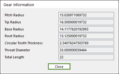
Figure 31.63 Gear Information dialog box
Draw: All data must be defined with respect to the tooth marker. You can move points graphically by using the mouse directly.
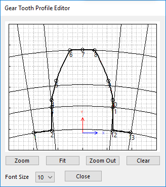
Figure 31.64 Gear Tooth Profile Editor dialog box
Generate optimal arc segment: In order to apply the modification of tooth, this button should be clicked.