39.2.2.1. Mesh Grid Setting
There are two types of mesh grid setting. First one is Mesh Grid on Cylinder and Second one is Mesh Grid on Piston.
In the case of Mesh Grid on Cylinder, mesh grid is distributed on the inner surface of cylinder as much as user set the number of mesh grid in circumferential and axial direction. Additionally, user can control Oil Hole & Groove Effects by designating mesh grid index as them.
In the case of Mesh Grid on Piston, user can make each mesh grid region and then, distribute the mesh grids in each region in circumferential and axial direction. Unlike the type of Mesh Grid on Cylinder, Oil Hole & Groove Effects is not taken account in this type.
Mesh Grid on Cylinder
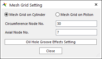
Figure 39.38 Mesh Grid on Cylinder in Mesh Grid Setting dialog box
Axial Node No.: “M”
Circumference Node No.: “N”
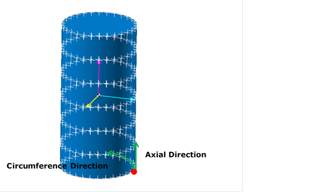
Figure 39.39 Defining Circumference Node No. and Axial Node No.
Oil Hole & Groove Effects Setting

Figure 39.40 Oil Hole & Groove Effects Setting dialog box
i-start: Defines start grid index in circumferential direction.
i-end: Defines end grid index in circumferential direction.
j-start: Defines start grid index in axial direction.
j-end: Defines end grid index in axial direction.
Pressure Type: Define pressure value on oil hole and groove region with constant value or time dependent expression.
Pressure: Defines the pressure value.
Color: Displays the selected grids as this color if the user checks View Nodes.
View Nodes: Shows the selected grids in the Working Window.
Figure 39.41 View Nodes
Update Selected Nodes: The position of Oil Hole and Groove is changed.
Mesh Grid on Piston
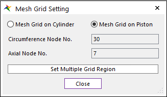
Figure 39.42 Mesh Grid on Piston in Mesh Grid Setting dialog box
Set Multiple Grid Region: In the case of Mesh Grid on Piston, you can set one or more grid settings to the desired area.
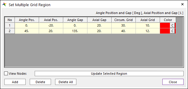
Figure 39.43 Set Multiple Grid Region dialog box
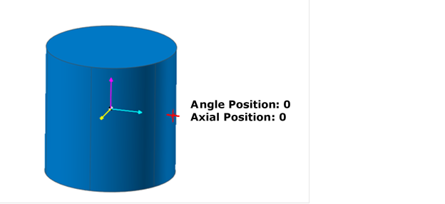
Figure 39.44 Initial Positions for the piston
Angle Pos.: Center position in the circumferential direction of the set grid region. The circumferential direction is defined as the rotation of the action marker from the X axis to the -Z axis.
Axial Pos.: Center position in the axial direction of the set grid region. The axial direction is defined as the Y axis of action marker.
Angle Gap: Circumferential direction extent of the grid region.
Axial Gap: Axial direction extent of the grid region.
Circum. Grid: Number of grids in circumferential direction of the grid region.
Axial Grid: Number of grids in axial direction of the grid region.
Color: Displays the selected grid as this color if the user checks View Nodes.
View Nodes: Shows the selected grids in the Working Window.
Update Selected Nodes: The grid regions are updated.
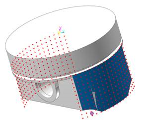
Figure 39.45 View Nodes