2.2.9.2. Basic Object Control
This tool is very useful to move some entities easily.
2.2.9.2.1. Translate
This is to translate entities.
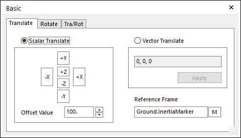
Figure 2.93 Basic dialog box [Translate]
Scalar Translate: If this option is checked, the selected entities are translated along the axis of the working plane marker or the specified marker, according the arrow used. You must indicate the amount of translation in Offset Value.
Vector Translate: If this option is checked, you must specify the amount of translation in the edit box as a vector form. You can move the entities by vector.
Reference Frame: Designates a reference frame marker so that selected entities can be translated along the axes of working plane marker or specified marker. If it is not defined, Ground.InertiaMarker becomes the reference frame.
Step to Translate an Entity
Click the Basic Object Control icon in the Advanced Toolbar.
Select the Translate tab in the Basic dialog box.
Select a type between Scalar Translate and Vector Translate.
In case of Scalar Translate,
Specify Offset Value.
Select an entity for Object Control.
Specify Reference Frame. If it is not defined, Ground.InertiaMarker becomes.
To move the entity, use Control button.
In case of Vector Translate,
Specify the amount of translation in the edit box as a vector form.
Select an entity for Object Control.
Specify Reference Frame. If it is not defined, Ground.InertiaMarker becomes.
Click Apply.
2.2.9.2.2. Rotate
This is to rotate entities.
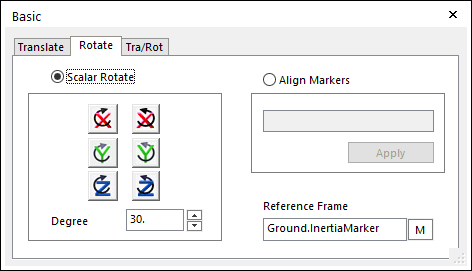
Figure 2.94 Basic dialog box [Rotate]
Scalar Rotate: If this option is selected, the selected entities are translated along the axis of the working plane marker or specified marker, according the used Rotate button. You must indicate the amount of rotation in the edit box. Rotate a set of selected entities along the axis of the dispatched Reference frame from the screen.
Align Markers: Aligns the orientation of the marker to Reference Marker. In order to use this option, you must check Align Markers tab in the dialog box, and then indicate the marker to align. You can use the M button to select the marker off the screen.
Reference Frame: Designate a reference frame marker so that selected entities can be rotated along the axis of the specified marker. If it is not defined, the inertia reference marker becomes the reference frame.
Step to Rotate an Entity
Click the Basic Object Control icon in the Advanced Toolbar.
Select the Rotate tab in the Basic dialog box.
Select a type between Scalar Rotate and Align Markers.
In case of Scalar Rotate,
Specify an angle.
Select an entity for Object Control.
Specify Reference Frame. If it is not defined, Ground.InertiaMarker becomes.
To move the entity, use the Control button.
In case of Align Markers,
Specify a marker belonging to the entity you want to rotate as Align Marker.
Select an entity for Object Control.
Specify Reference Frame. If it is not defined, Ground.InertiaMarker becomes.
Click Apply, and then the selected entity aligns to the orientation of the reference marker.
Note
2.2.9.2.3. Tra / Rot
This is to translate and rotate the marker.
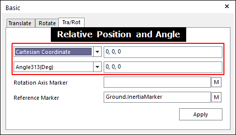
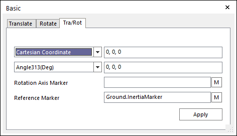
Figure 2.95 Basic dialog box [Tra/Rot]
Relative Position: Specifies the type of coordinate and the value of coordinate. The relative position between Rotational Axis Marker and Reference Marker are calculated automatically with respect to Reference Marker.
Relative Angle: Specifies the type of euler angle and the value of euler angle. The relative angle between Rotational Axis Marker and Reference Marker are calculated automatically with respect to Reference Marker.
Rotational Axis Marker: Specifies a rotational axis marker in the selected entities.
Reference Marker: Specifies a reference marker. If it is not defined, Ground.InertiaMarker becomes the reference marker.
Step to Translate and Rotate an Entity
Click the Basic Object Control icon in the View Control Toolbar.
Select the Tra/Rot tab in the Basic dialog box.
Select a Rotational Axis Marker.
Specify Reference Frame. If it is not defined, Ground.InertiaMarker becomes. And then the coordinate and the angle are updated automatically with respect to Reference Marker.
Modify the coordinate and the angle in the relative position and angle to translate or rotate.
Select an entity for Object Control. The Rotate Axis Marker has to be include in the selected entity.
Click Apply. And then the selected entity is moved by the amount of offset to relative position and angle with respect to the reference marker.