26.5.2. Properties
The Beam Assembly property page is shown in Figure 26.32. And its parameters are explained below. The user can modify properties for the beam such as geometry information, FFlex body characteristics, boundary condition, and output. The general pages such as General Page, Graphic Property Page, Origin and Orientation Page are same with general body.
FE Info (Refer to FEInfo. in FFlex)
Connecting Parameter (Refer to Connecting Parameter in FFlex)
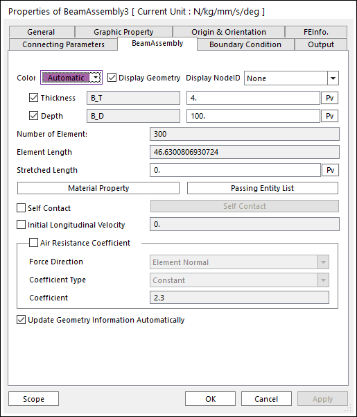
Figure 26.32 Beam Assembly property page [BeamAssembly page]
Color: Changes the color of line.
Display Geometry: If this function is not checked, only the assembly line is displayed.
Display Node ID: Choose the type to display Node ID as None or All or S/End.
None : No nodes belong to the displaying segment.
All : all nodes belong to the displaying segment.
S/End : Only start and End nodes belong to the displaying segment.
Lower Thickness: Defines the lower thickness of segment.
Upper Thickness: Defines the upper thickness of segment.
Number of Elements: Defines the number of force elements to connect nodes. This can be defined only when the beam assembly is made.
Element Length: Defines the length of element. This can be defined only when the beam assembly is made.
Stretched Length: Defines the stretched length from the initial length.
Initial length = element length-stretched length
Material Property: Allows the user to access the dialog box defining the material property of segments. Refer to Material Property.
Passing Entity List: Defines geometries contacted segments.
Self Contact: When the roll to roll system is assembled as the open loop, this option is activated. Refer to Beam Assembly Self Contact.
Initial Longitudinal Velocity: Defines the initial velocity in the longitudinal direction of segments.
Air Resistance Coefficient: Because the workpiece is very light, the dynamics of the workpiece is much influenced by the air. The value of air resistance coefficient is the ratio of the resistance force to the kinetic energy of the air in the workpiece. The user can select two types of expression and constant. Also user can select the force direction, velocity or element normal.
Force Direction
Velocity : Opposite direction of Velocity for each node.
Element Normal : Opposite direction of element Normal direction.
Expression: Show expression list used for air resistance coefficient.
Constant: Show constant value used for air resistance coefficient
Update Geometry Information Automatically: If this option is unchecked, the position and orientation of the geometry constituting the group are not updated depending on variables in the property page. So, after executing Extract function, this option is unchecked.