39.1.2. Properties
The user can modify the property of EHD Rotational Lubrication in the following dialog box.
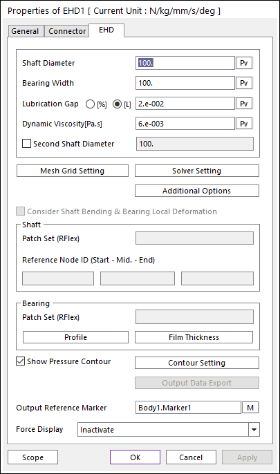
Figure 39.4 EHD Rotational Lubrication property page [EHD page]
Shaft Diameter: Defines a shaft diameter of EHD Rotational Lubrication.
Bearing Width: Defines a bearing width of EHD Rotational Lubrication.
Lubrication Gap: Defines a characteristic of EHD.
[%]: Defines this value using the percentage method.
\(Lubrication\ Gap(\%)=\frac{Lubrication\ Gap(mm)}{Journal\ Diameter(mm)}\times 100\)
Eq1. Equation of Lubrication Gap
[L]: Defines this value as length unit.
Dynamic Viscosity [Pa.s]: Defines lubricant viscosity.
Second Shaft Diameter: If this option is defined, it is possible to make the cone shape shaft.
Mesh Grid Setting: Defines mesh grids for Oil Hole and Groove Effects. For more information, click here.
Additional Options: Defines viscosity information, boundary pressure and asperity contact information. Also, Flexible effect can be given. For more information, click here.
Solver Setting: Defines parameters related to EHD Pressure Convergence. For more information, click here.
Consider Shaft Bending & Bearing Local Deformation: If this option is checked, RecurDyn/Solver computes bending shape of shaft based on reference nodes of it and local deformation of bearing. And then, RecurDyn/Solver reflects on this effect in order to compute local film thickness and evaluate hydrodynamic pressure.
Shaft: User has to set RFlex patch to defined lubrication region of shaft. And then, user have to 3 reference nodes in order to compute bending shape of shaft. We recommend that 3 Reference nodes are located on the both end and middle position of shaft.
Patch Set(RFlex): Selects a patch set in which lubrication region of shaft is defined.
Reference Node ID(Start- Mid. - End): Select a reference nodes which is used for base nodes in order to define bending shape of shaft. We recommend that start node is located at the end of the negative z direction of action marker and end node is located at the end of the positive z direction of action marker. In the case of middle node, it is recommended that middle node is located at the same position of action marker.
Bearing: User can set RFlex patch to define lubrication region of bearing. If using RFlex patch, 1 reference node should be defined. It is used for reference frame in order to define bearing local deformation for nodes in lubrication region. For more information, click here.
Patch Set(RFlex): Selects a patch set in which lubrication region of bearing is defined.
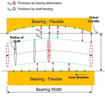
Figure 39.5 Schematic diagram of shaft bending and bearing local deformation of nodes in lubrication region.
Profile: Defines a offset data in angle and height coordinate. User can apply arbitrary cylinder shape to EHD analysis by setting this offset table data.
Film Thickness: Define oil film thickness by boundary condition.
Show Pressure Contour Animation: If this option is checked, the user can see the EHD contour during the playing animation.
Contour Setting: Defines the EHD Contour information. For more information, click here.
Output Data Export: Displays on Scope or exports for the film thickness and file pressure. For more information, click here.
Output Reference Marker: Selects a reference marker for EHD force result. The default marker is a base marker of EHD.
Force Display: The user can graphically display the resultant force vector on the Working Window.
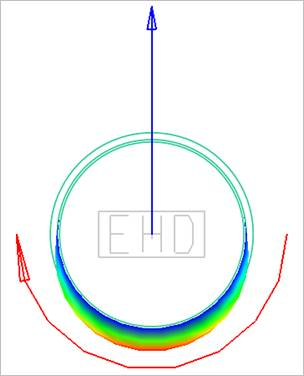
Figure 39.6 Force Display of EHD Rotational Lubrication