28.2.1. Sprocket
In general, a low mobility tracked vehicle employs a single sprocket consisting of teeth and the main body that is named the sprocket hub. The exact sprocket tooth geometry can be defined. Sprocket tooth geometric entity data can be created, edited, exported or imported from a predefined data file.
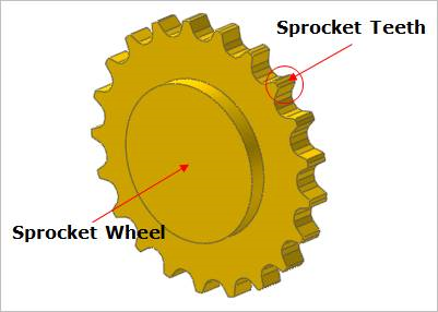
Figure 28.7 Sprocket geometric entity
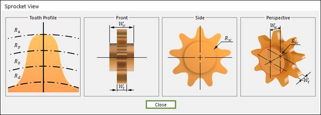
Figure 28.8 Sprocket dimension information
Rw |
Sprocket Wheel Radius |
Wt |
Width of the Teeth |
Ww |
Width of the outer edges of the hub |
Rd |
Dedendum Circle Radius |
Rb |
Base Circle Radius |
Rp |
Pitch Circle Radius |
Ra |
Addendum Circle Radius |
28.2.1.1. Modeling Options
The user can create a sprocket as follows.
Point, WithDialog
Point: Selects a point to define the center of the sprocket.
WithDialog: Modifies the property for the sprocket. The sprocket is created with clicking OK.
28.2.1.2. Properties
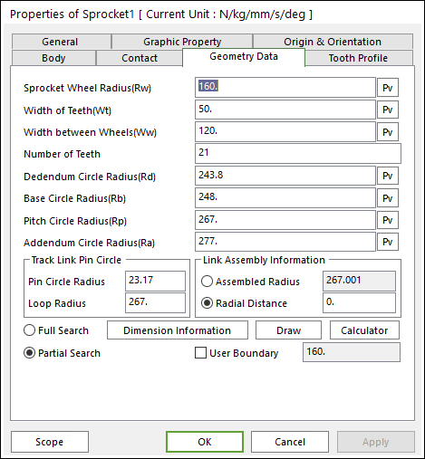
Figure 28.9 Sprocket property page [Geometry Data page]
The Sprocket property page is shown in Figure 28.9. The parameters are explained below. In order to understand the geometry, refer to Dimension Information.
Sprocket Wheel Radius(Rw): Enters the wheel radius of sprocket.
Width of Teeth(Wt): Enters the teeth width of sprocket.
Width between Wheels(Ww) : Enters the width of outer edges of the hub.
Number of Teeth: Enters the number of teeth.
Dedendum Circle Radius(Rd): Enters the dedendum circle radius of tooth profile.
Base Circle Radius(Rb), Pitch Circle Radius(Rp), Addendum Circle Radius(Ra): These values can help to modify the shape of sprocket tooth easily as baseline in Sprocket Editor dialog and it is used in the TVLM Calculator dialog. It does not change the sprocket geometry directly.
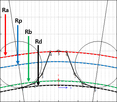
Figure 28.10 Ra, Rp, Rb, Rd in Sprocket Editor
Pin Circle Radius, Loop Radius: These data must be defined with respect to the sprocket tooth marker. And these values can help to modify the shape of sprocket tooth easily as baseline in Sprocket Editor dialog and it is used in the TVLM Calculator dialog. It does not change the sprocket geometry directly.
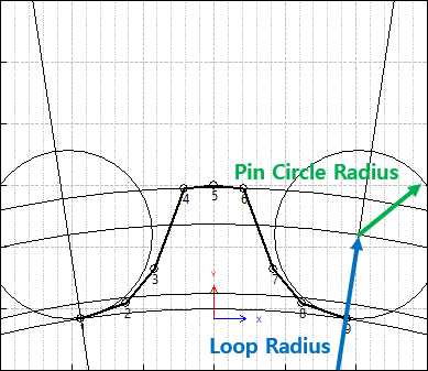
Figure 28.11 Pin Circle Radius and Loop Radius
Link Assembly Information: The gap between link pins and sprocket teeth can be controlled by Assembled Radius or Radial Distance.
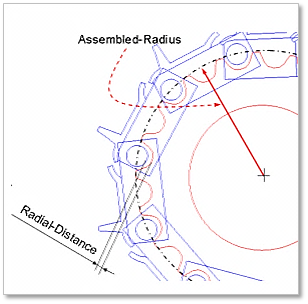
Figure 28.12 Sprocket profile
Full Search : Search for the contact of all track link
Partial Search : Search for the contact of the neighbor track link
User Boundary: Define the radius of neighbor range.
Note: When the user checks Partial Search, Searching for contact of between sprocket and links is available in specific boundary. It is used to reduce the total solving time. If the user checks User Boundary, the user can change the value of boundary radius. And if the user does not use it, the value of boundary radius is set internally.
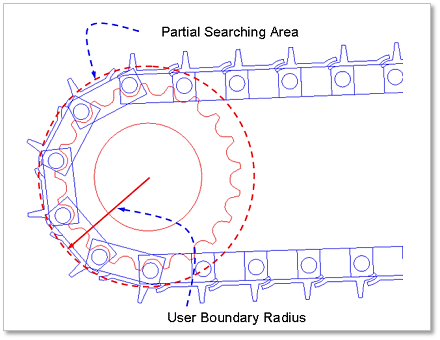
Figure 28.13 Partial searching area & user boundary
28.2.1.2.1. Tooth Profile
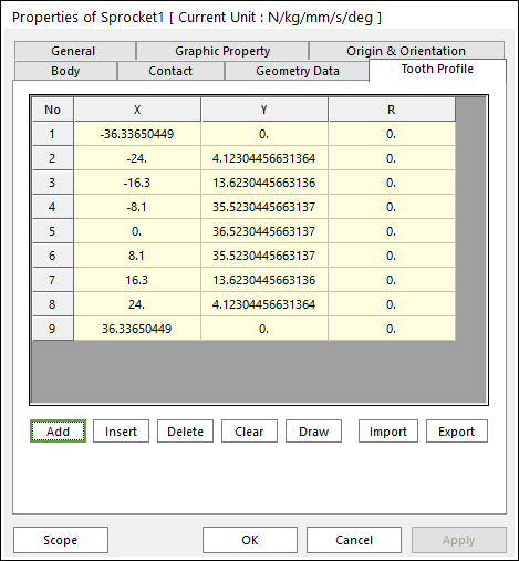
Figure 28.14 Sprocket property page [Tooth Profile page]
X, Y, R: Defines points and radius.
Add Row: Adds a row to the end of the table.
Insert Row: Inserts a row where the cursor is and move the current and later rows down.
Delete Row: Deletes the row where the cursor is and move the later rows up.
Clear: Deletes all rows in the table.
Draw: All data must be defined with respect to the sprocket tooth marker. You can move points graphically by using the mouse directly.
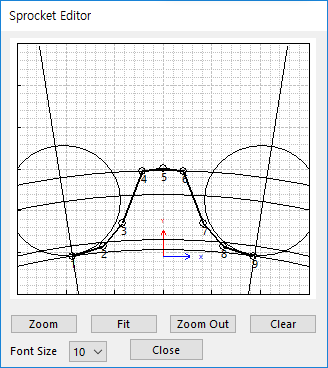
Figure 28.15 Sprocket Editor dialog box
Import: Imports the X, Y, and R data pairs from a CSV file or a MAT file or a text file. In the case of the text file, the usage of the comma, the tab, and the space can be the delimiter between the three columns in the file. And when using the Excel file, the user can select the Tab-delimited text file output option or the CSV (Comma-Separated Values) file output option to save the Excel file which can be imported.
Export: Exports the X, Y, and R data pairs to a CSV file or a MAT file or a text file.
Contact between a Sprocket and Track Links
The sprocket is in contacts with the track link in the two parts.
The track link pin - the sprocket teeth surface
The inner surface of track link - the sprocket teeth side
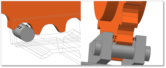
Figure 28.16 Contact between a sprocket and track links