29.2.3. Ribbed V-Belt
The continuous belt system is modeled by belt segments and the matrix force element.
A matrix force is used to connect two segments of the belt system. You must create the one-reference belt segment from all belt segments. (All belt segments are copied.)
Once the belt segment is created, it is registered as clone body.
The inertial properties of the assembled belt segments are automatically duplicated to be the same as values of the clone body.
The belt properties should be defined carefully prior to assembling the belt system.
The matrix force connecting two belt segments is automatically created when the belt system is assembled.
Geometric Ribbed V-Belt
The geometric information provided by user is used for both the display and contact force computation in the solver. The V-Belt enables contact between the flat as the upper face and the V-shaped lower faces to the other entities of belt assembly. The contact normal forces are used to compute the friction among the belt and the pulleys.
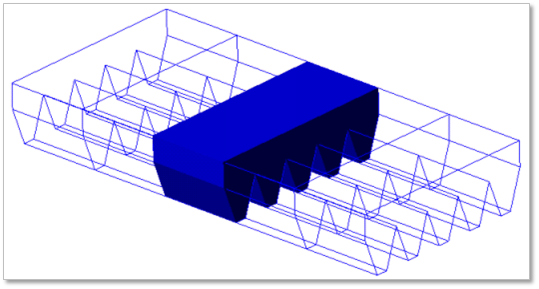
Figure 29.19 Ribbed V-Belt geometric entity
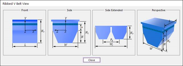
Figure 29.20 Ribbed V-Belt dimension information
H |
Belt Height |
Ht |
Belt Thickness |
Hr |
Rib Height |
W |
Belt Width |
A |
Belt Angle |
Pb |
Pitch |
L |
Belt Segment Length |
a |
Cord Distance |
29.2.3.1. Modeling Options
The user can create a belt as follows.
Point, WithDialog
Point: Selects a point on Ground to define the belt. It doesn’t matter where the belt is because the created body is a clone body for segment assembly.
WithDialog: Modifies the property for the belt. The belt is created with clicking OK.
29.2.3.2. Properties
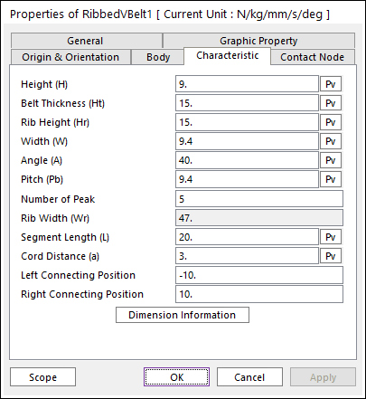
Figure 29.21 Ribbed VBelt property page [Characteristic page]
The Ribbed VBelt property page is shown in Figure 29.21. The parameters are explained below. In order to understand the geometry, refer to Dimension Information.
Height (H): Enters the height of the ribbed V-belt. The height is larger than 0.
Thickness (Ht): Enters the belt thickness of the ribbed V-belt. The belt thickness is larger than H.
Rib Height (Hr): Enters the total belt height of the ribbed V-belt. The rib height is larger than Ht.
Width (W): Enters the width of the ribbed V-belt. The width is larger than 0.
Angle (A): Enters the angle of the ribbed V-belt. The angle is larger than 0. The angel is smaller 2*atan (W/(2*H)). The bottom width of ribbed V-belt is W-2*H*tan (A/2). [Degree]
Pitch (Pb): Enters the pitch of the ribbed V-belt. The pitch is larger than W.
Number of Peak: Enters the number of peak in the ribbed V-belt.
Rib Width (Wr): Pb * Number of peak
Segment Length (L): Enters the length of ribbed V-belt. The length is larger than 0.
Cord Distance (a): Enters the cord distance of ribbed V-belt.
Left Connecting Position: Enters the left position of connecting force. The reference frame of the position is the geometry reference frame of belt.
Right Connecting Position: Enters the right base position of connecting force. The reference frame of the position is the geometry reference frame of belt.
Note
The ribbed V-belt and the ribbed V-pulley entities are not defined to be symmetrical along the normal axis, because the reference coordinate system is in the middle of the first rib or groove (not the center rib or groove). So, if you want to assemble a ribbed V-belt or V-pulley with other belt toolkit entities, you need to move the ribbed V-belt & ribbed V-pulley along the normal axis to align them.
Contact Node
The Ribbed V-Belts contact pulley, roller and flange to contact node.
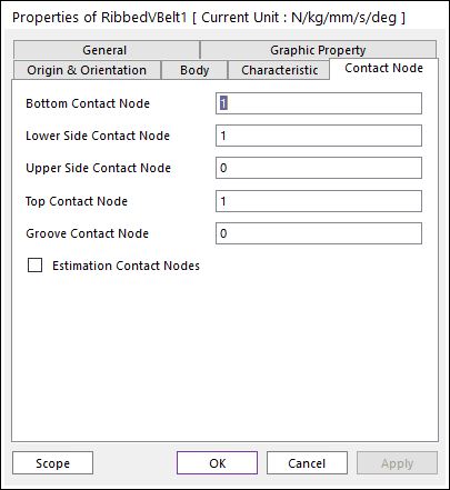
Figure 29.22 Ribbed VBelt property page [Contact Node page]
Bottom Contact Node: Enters the number of nodes for the belt bottom.
Lower Side Contact Node: Enters the number of nodes for the belt lower side.
Upper Side Contact Node: Enters the number of nodes for the belt upper side.
Top Contact Node: Enters the number of nodes for the belt top.
Groove Contact Node: Enters the number of nodes for the belt groove.
The number of bottom contact nodes is 2.
The number of lower side contact nodes is 2.
The number of upper side contact nodes is 2.
The number of top contact nodes is 2.
The numbers of groove contact nodes are 1.
Contact point of segment belt is located in the center
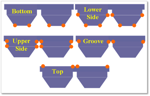
Figure 29.23 Contact node
Estimation Contact Nodes: If this check box is checked, contact nodes are set as followings. And dialog input parameters are neglected.
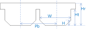
Figure 29.24 (H, Ht, Hr, W, and Pb) definitions
If ((Ht==Hr) or (W==Pb)) :
Bottom Contact Node : 2
Lower Side Contact Node : 2
Upper Side Contact Node : 2
Top Contact Node : 2
Groove Contact Node : 0
Else if (Ht==H) :
Bottom Contact Node : 2
Lower Side Contact Node : 2
Upper Side Contact Node : 0
Top Contact Node : 2
Groove Contact Node : 2
Else :
Bottom Contact Node : 2
Lower Side Contact Node : 2
Upper Side Contact Node : 2
Top Contact Node : 2
Groove Contact Node : 2