29.2.4. Timing Belt
The continuous belt system is modeled by belt segments and a matrix force element. The matrix force is used to connect two segments of the belt system. You must create the one-reference belt segment from all belt segments. (All belt segments are copied.)
Once the belt segment is created, it is registered as clone body.
The inertial properties of the assembled belt segments are automatically duplicated to be the same as values of the clone body.
The belt properties should be defined carefully prior to assembling the belt system.
The matrix force connecting two belt segments is automatically created when the belt system is assembled.
Geometric Timing belt
The geometric information provided by user is used for both the display and the contact force computation in the solver.
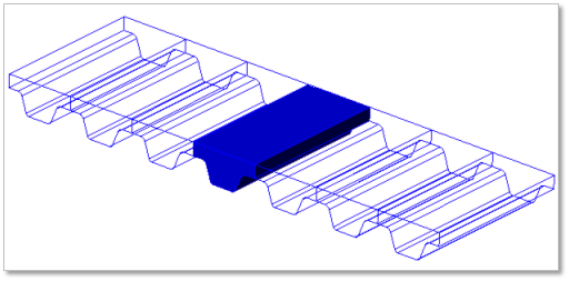
Figure 29.25 Timing belt geometric entity
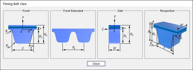
Figure 29.26 Timing belt dimension information
Pb |
Pitch |
W |
Belt Width |
a |
Cord Distance |
A |
Belt Angle |
S |
Tooth Length |
Ht |
Tooth Height |
Hs |
Nominal Height |
Rr |
Tooth Root Radius |
Ra |
Tooth Tip Radius |
29.2.4.1. Modeling Options
The user can create a belt as follows.
Point, WithDialog
Point: Selects a point on Ground to define the belt. It doesn’t matter where the belt is because the created body is a clone body for segment assembly.
WithDialog: Modifies the property for the belt. The belt is created with clicking OK.
29.2.4.2. Properties
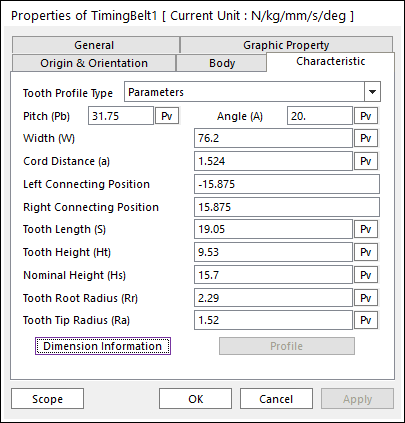
Figure 29.27 Timing Belt property page [Characteristic page]
The Timing Belt property page is shown in Figure 29.27. The parameters are explained below.
Tooth Profile Type: 2 types are supported in RecurDyn/Belt.
General Type
This method is used when the timing belt shape with an arbitrary tooth profile is needed.
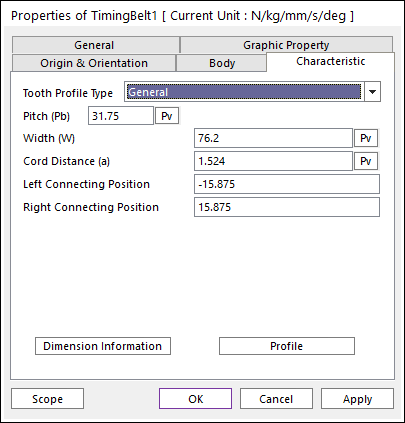
Figure 29.28 Timing Belt property page [General type]
Pitch (Pb): Enters the pitch in the timing belt.
Width (W): Enters the width of the timing belt.
Left Connection Position: Enters the left position of connection force. The reference frame of position is the geometry reference frame of belt.
Right Connection Position: Enters the right base position of connection force. The reference frame of position is the geometry reference frame of belt.
Profile
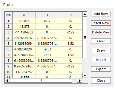
Figure 29.29 Profile dialog box
X,Y,R: Defines points and radius. All data must be defined with respect to the profile marker.
Add Row: Adds a row to the end of the table.
Insert Row: Inserts a row where the cursor is and move the current and later rows down.
Delete Row: Deletes the row where the cursor is and move the later rows up.
Clear: Deletes all rows in the table.
Draw: Shows the defined profile. The user can move points graphically by using the mouse directly.
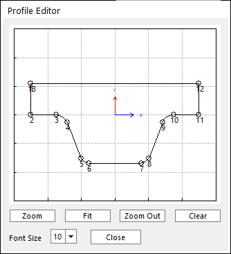
Figure 29.30 Profile Editor dialog box
Import: Imports the X, Y, and R data pairs from a CSV file or a MAT file or a text file. In the case of the text file, the usage of the comma, the tab, and the space can be the delimiter between the three columns in the file. And when using the Excel file, the user can select the Tab-delimited text file output option or the CSV (Comma-Separated Values) file output option to save the Excel file which can be imported.
Export: Exports the X, Y, and R data pairs to a CSV file or a MAT file or a text file.
Parameter
This method is used when the timing belt shape with ISO 5294 is needed.
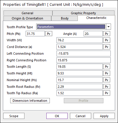
Figure 29.31 Timing Belt property page [Parameter type]
In order to understand the geometry, refer to Dimension Information.
Pitch (Pb): Enters the pitch in the timing belt.
Width (W): Enters the width of the timing belt.
Left Connection Position: Enters the left position of connection force. The reference frame of position is the geometry reference frame of belt.
Right Connection Position: Enters the right base position of connection force. The reference frame of position is the geometry reference frame of belt.
Angle (A): Enters the angle of the timing belt. [Degree]
Tooth Length (S): Enters the tooth length of timing belt.
Tooth Height (Ht): Enters the tooth height of timing belt.
Nominal Height (Hs): Enters the nominal height of timing belt.
Tooth Root Radius (Rr): Enters the tooth root radius of timing belt.
Tooth Tip Radius (Ra): Enters the tooth tip radius of timing belt.