42.2.2.1.2. Assembly Clone & Assembly
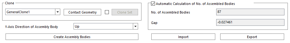
Figure 42.16 Assembly Clone & Assembly
Contact Geometry: Define the contact geometry of the assembly body that is in contact with the passing body.
Note
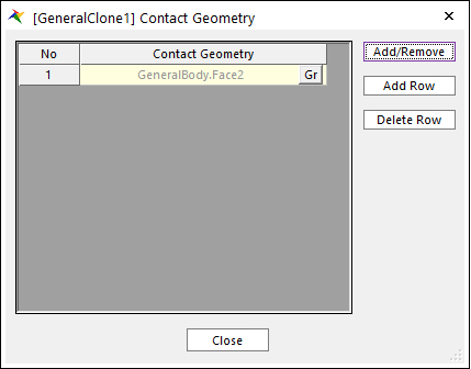
Figure 42.17 Definition of Contact Geometry dialog box
Clone Set: Check to define multi-clone set.
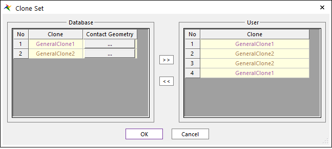
Figure 42.18 Definition of Clone Set dialog box
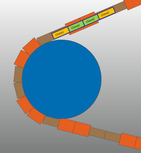
Figure 42.19 Example of Clone Set
Y-Axis Direction of Assembly Body: Change the assembly direction by changing the Y-Axis of the assembly body.
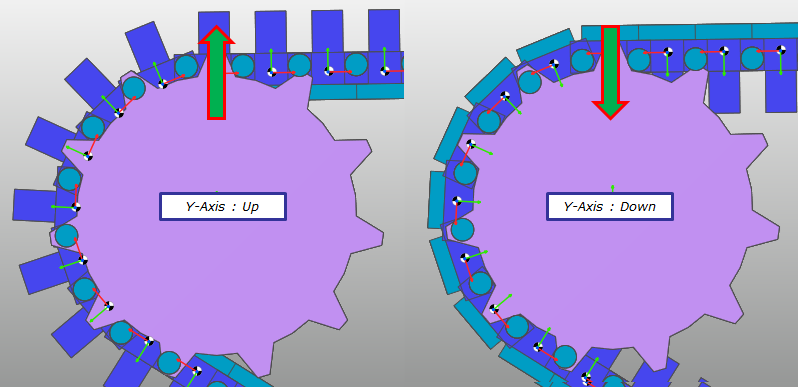
Figure 42.20 Definition of Y-Axis Direction
Automatic Calculation of No. of Assembled Bodies: If you click Create Assembly Bodies with the checked this option, the number of assembly bodies is set automatically.
No. of Assembled Bodies: Modify the number of Assembled Bodies.
Gap: Show a value of gap.
Import: Import assembly-related settings including information such as passing body and clone.
Export: Export assembly-related settings including information such as passing body and clone.