33.1.1. Step to define Global Data
Click the Data icon of the Piston group in the Piston tab. The user can see the Pre Piston Global Data Dialog.
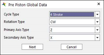
Figure 33.2 Pre Piston Global Data dialog box
Cycle Type: Selects the engine cycle 2 or 4 stroke. Cycle Type is related with Firing Angle and Gas pressure profile.
In the 2 stroke engine system, a process of ‘Suction – Compression – Explosion – Exhaust’ occurs during the 1 rotation of crank shaft.
In the 4 stroke engine system, the process occurs during the 2 rotation of crank shaft.
Primary Axis Type: Select the axis which direction can be the rotating axis of crank shaft.
Secondary Axis Type: Select the axis which direction can be the cylinder’s direction.
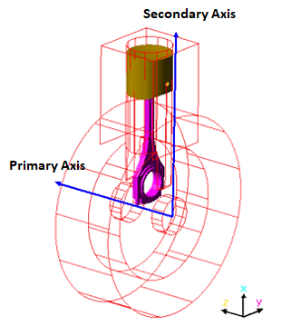
Figure 33.3 Primary & Secondary Axis of Piston System
Number of Cylinder: Enter the value of the number of cylinders that can be created.
Previous defined values are the basic information to create the piston system. After these data are confirmed, each value is unchangeable. So, if Next is clicked, the warning message is displayed.
After that, the Piston Global Data Dialog is opened.
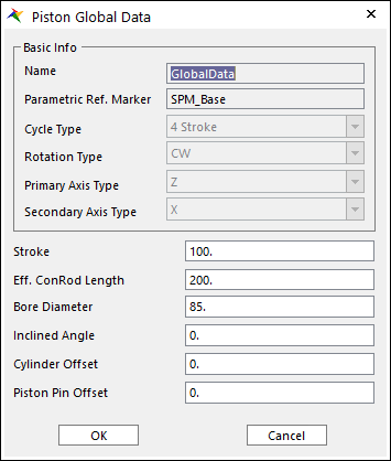
Figure 33.4 Piston Global Data dialog box
Name: Means that the values the user entered are defined in Global Data.
Parametric Ref. Marker: Checks the parametric marker for crank system. SPM_Base controls the whole system. It cannot be modified.
Stroke: Is a distance between TDC (Top Dead Center) and BDC (Bottom Dead Center). If you change the value of Stroke, rotation diameter of Crank Shaft Pin can be changed to be same with the value of Stroke.
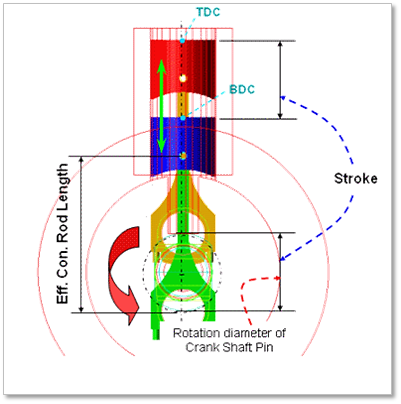
Figure 33.5 Stroke of an engine
Eff.Con. Rod Length: Is the distance between the center point of crankshaft’s pin body and piston pin.
Bore diameter: This value is a diameter of cylinders. If you change this value, a piston head diameter is also changed. Because the values are defined by SPV_Cylinder_Diameter_i which is Special Parametric Value.
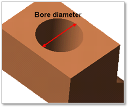
Figure 33.6 Bore Diameter
Inclined Angle: Please refer to the below Figure.
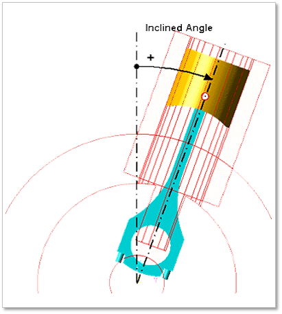
Figure 33.7 Inclined Angle
Cylinder Offset & Piston Pin Offset: Please refer to the below Figures.
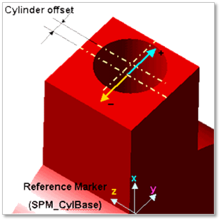
Figure 33.8 Cylinder offset
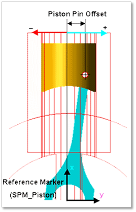
Figure 33.9 Piston pin offset
After setting all parameters, click OK.
The user can define the geometric and connection information using the Component Builder.