6.2.3.3. Inplane
An inplane joint constraints the origin of the action marker to lie on the x-y plane of the base marker, as shown in Figure 6.206.

Figure 6.206 Definition of Inplane Joint
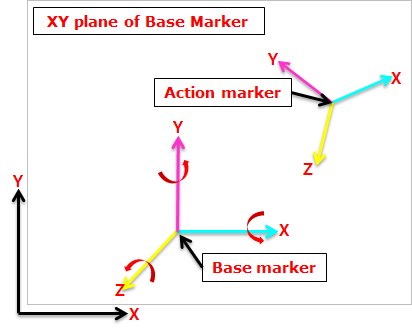
Figure 6.207 Definition of Inplane Joint
6.2.3.3.1. Modeling Options
The user can create a joint entity as follows.
Point, Direction
Point: Selects a point on two bodies to define the location of the inplane joint.
Direction: Defines the z-axes of base and action markers.
Body, Body, Point, Direction
Body: Selects a base body of the inplane joint.
Body: Selects an action body of the inplane joint.
Point: Selects a point to define the location of the inplane joint.
Direction: Defines the z-axes of base and action markers.
6.2.3.3.2. Properties
The user can only define the force display using the Joint page.
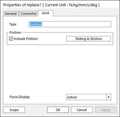
Figure 6.208 Inplane property page [Joint page]
Type: Shows the type of joint.
Force Display: Displays the resultant force vector graphically on Working Window.
6.2.3.3.2.1. Joint Friction
This defines the friction force which contains the stiction algorithm on the inplane joint. Include Friction option in Joint property page must be checked and Sliding and Stiction is selected to use the friction force.
Figure 6.209 Inplane Joint property page [Sliding & Stiction type]
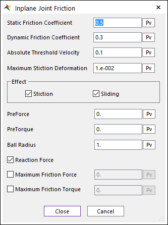
Figure 6.210 Inplane Joint Friction dialog box
The frictional torque is calculated according to the following equation:
\({{F}_{friction}}=\mu ({{F}_{reaction}}+(1/{{\mu }_{s}}){{F}_{preForce}})\)
\({{T}_{friction}}=\mu ({{R}_{ball}}{{F}_{reaction}}+({{R}_{ball}}/{{\mu }_{s}}){{F}_{preForce}}+(1/{{\mu }_{s}}){{T}_{preTorque}})\)
Where, the inputs into the equation are defined in the following table:
Current Friction Coefficient |
\(\mu\) |
The coefficient of friction calculated during the simulation is a function of the relative velocity between body surfaces. |
Static Friction Coefficient |
\({{\mu }_{s}}\) |
The coefficient of friction is zero at a zero velocity, but it smoothly transitions to the static coefficient of friction at Absolute Threshold Velocity (\(\Delta v\)). |
Effect |
Checks Stiction or Sliding \({{\mu }^{sliding\text{ }only}}=-{{\mu }_{v}},\text{ }{{\mu }_{v}}^{\max }={{\mu }_{d}}\)
\({{\mu }^{stiction\text{ }only}}=-\left( 1-\beta \right){{\mu }_{\delta }}-{{\mu }_{v}},\text{ }{{\mu }_{v}}^{\max }={{\mu }_{s}}\)
For more information, click here. |
|
Pre Force |
\({{F}_{preload}}\) |
A constant frictional force that acts during the entire simulation. |
Reaction Force |
\({{F}_{reaction}}\) |
The force in the joint calculated during the simulation in the direction normal to the translational axis or XY plane. |
Pre Torque |
\({{T}_{preload}}\) |
A constant frictional torque that acts during the entire simulation. |
Ball Radius |
\({{R}_{ball}}\) |
The average distance or radius from the origin of the spherical axis. |
Maximum Friction Force |
\({{F}_{\max }}\) |
Collisions during contact as well as transitions during sliding forces can result in force spikes. High frictional forces can result from these spikes. This option allows a maximum friction force to be defined that should correspond to the maximum expected steady-state force. |
Maximum Friction Torque |
\({{T}_{\max }}\) |
Collisions during contact as well as transitions during sliding forces can result in force spikes. High frictional torques can result from these spikes. This option allows a maximum friction torque to be defined that should correspond to the maximum expected steady-state force. |
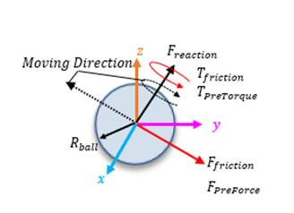
As the result of Inplane joint friction, FX_Friction_Force, FY_Friction_Force, TX_Friction_Torque, TY_Friction_Torque, and TZ_Friction_Torque are shown. The reference frame that defines the axis of the result values is the base marker of the joint, not the inertia reference frame (Ground.InertiaMarker).
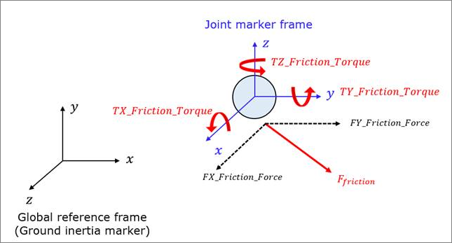
Figure 6.211 Reference frame that defines the axis of the result of Inplane joint