34.2.3. SwingArm - ArmShaft Type
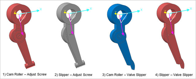
Figure 34.106 SwingArm - ArmShaft
34.2.3.1. Properties
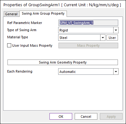
Figure 34.107 Swing Arm property page
Ref Parametric Marker: Controls the position of Swing Arm. It is also special parametric marker (SPM).
Type of Swing Arm: Selects the type of Swing Arm. It defines the connection method between multi bodies.
Material Type: Selects a material type. Three method are supported. For more information, click here.
Swing Arm Geometry Property: Defines some geometry data and property data for Swing Arm. Cam Roller and Slipper types are supported and the type can be selected in Valve Global Data dialog box.
Each Rendering: The selected mode can be displayed in Each Render mode.
34.2.3.1.1. Type of Swing Arm
Rigid Type
All multi bodies are connected by fixed joint. It acts like one body.
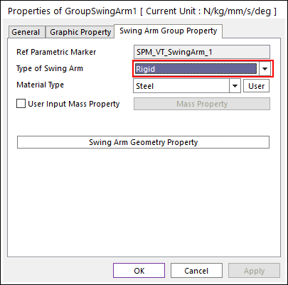
Figure 34.108 Swing Arm property page [Rigid Type]
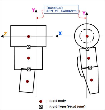
Figure 34.109 Rigid Type of the Swing Arm
Torsional & Bending Type
Multi bodies are connected by Bushing Force. It acts like flexible body.
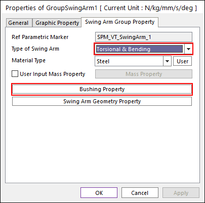
Figure 34.110 Swing Arm property page [Torsional & Bending Type]
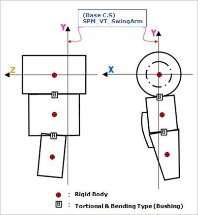
Figure 34.111 Torsional & Bending Type of the SwingArm
The user can modify the property of bushing force that connects multi bodies. For more information, refer to Bushing Force.
If the user clicks Bushing Property, the user can see the following dialog box.
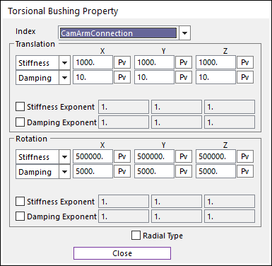
Figure 34.112 Torsional Bushing Property dialog box
Beam Type
Multi bodies are connected by Beam Force. It acts like flexible body.
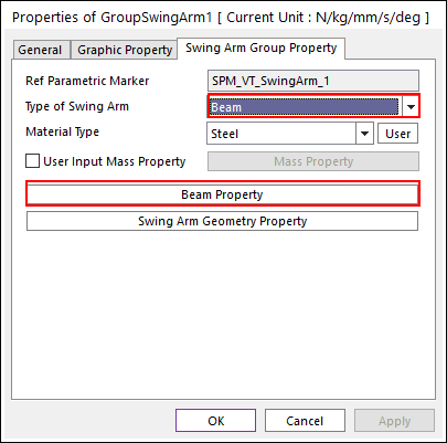
Figure 34.113 Swing Arm property page [Beam Type]
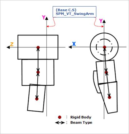
Figure 34.114 Beam Type of the Swing Arm
The user can modify the property of Beam Force that connects multi bodies. The user has to specify the value of Shear Modulus that is used to calculate Beam Force. For more information, refer to Beam Force.
If the user clicks Beam Property, the user can see the following dialog box.
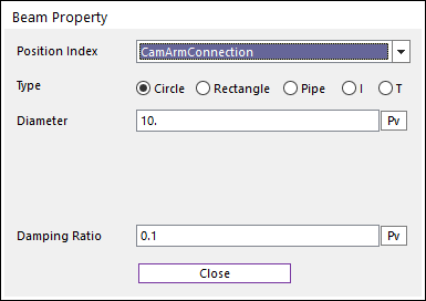
Figure 34.115 Beam Property dialog box
34.2.3.1.2. Swing Arm Geometry Property

Figure 34.116 SwingArm [CamRoller – Shaft] Property dialog box [CamRoller – AdjustScrew Type]
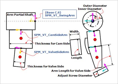
Figure 34.117 Geometric Information
Arm Thickness of Cam Side: Defines a thickness of arm for Cam Side.
Arm Length: Defines a length of arm for Valve Side.
Arm Thickness: Defines a thickness of arm for Valve Side.
AS Diameter: Defines a diameter of Adjust Screw.
VS Length: Defines a length of Valve Slipper.
VS Width: Defines a width f Valve Slipper.
Arm Partial Shaft
Arm Partial Shaft Outer Diameter: Defines an outer diameter of Arm Partial Shaft.
Arm Partial Shaft Inner Diameter: Defines an inner diameter of Arm Partial Shaft.
CamRoller Type
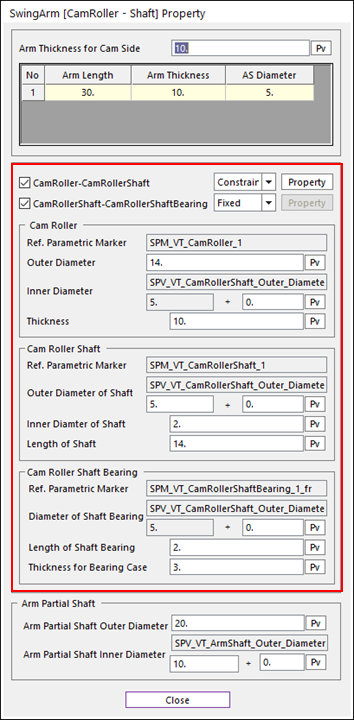
Figure 34.118 SwingArm [CamRoller – Shaft] Property dialog box
All data for Cam Roller, Cam Roller Shaft, and Cam Roller Shaft Bearing are same to CamRoller Type of Rocker Arm Geometry Property.
Slipper Type
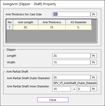
Figure 34.119 SwingArm [Slipper – Shaft] Property dialog box
All data for Slipper are same to Slipper Type of Rocker Arm Geometry Property.